
| Tweet |

Custom Search
|
|

|
||
 TM 55-1905-223-24-5
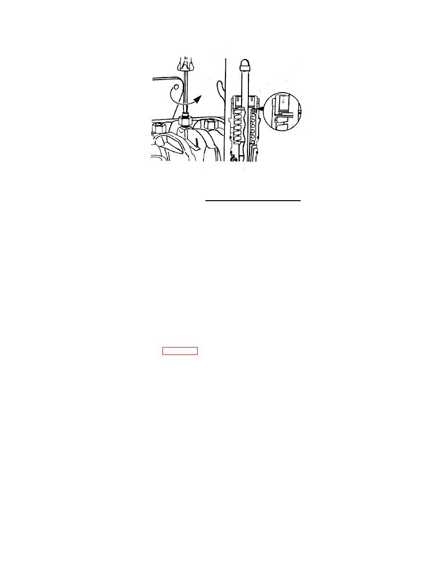
FIGURE 2-43. Injector Adjusting Screw .
(f)
Tighten the adjusting screw to 5 to 6 in-lb torque using torque wrench.
(g)
Hold the adjusting screw in position. The adjusting screw must not turn when the locknut is tightened.
Tighten the locknut to the following torque values:
1
With torque wrench adapter - 35 ft lb.
2
Without torque wrench adapter - 45 ft-lb.
(h)
Adjust the crossheads and the valves on cylinder No. 5 before rotating the accessory drive to the next
valves set mark. Refer to "Crosshead Adjustment" and "Valve Adjustment" in this procedure.
(i)
After adjusting the crossheads and the valves on cylinder No. 5, rotate the accessory drive and align
the next valve set mark on the accessory drive pulley with the pointer on the gear cover.
(j)
Adjust the appropriate injector, the crossheads, and the valves following the Injector and Valve
Adjustment Sequence Chart (Table 2-3).
(5)
Crosshead Adjustment.
NOTE
Crosshead adjustment must always be made before attempting to adjust the valves.
2-124
|
||
|
||


