
| Tweet |

Custom Search
|
|

|
||
 TM 55-1905-223-24-5
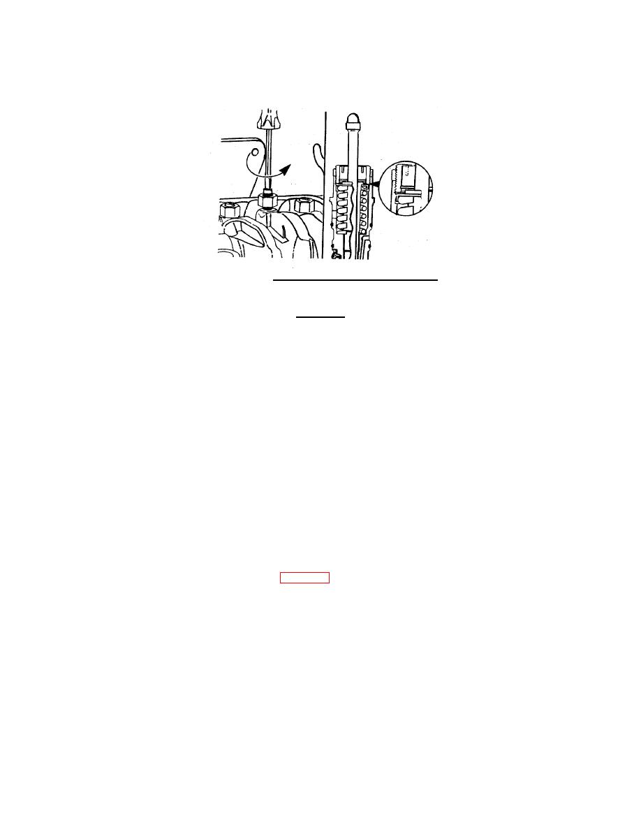
FIGURE 3-26. Loosening Injector Adjusting Screw .
CAUTION
An overtight setting on the injector adjusting screw will produce increased stress on
the injector train and the camshaft injector lobe which can result in engine damage.
(f) Tighten the adjusting-screw to 5 to 6 in-lbs (0.56 to 0.68 N ) torque.
m
(g) Hold the adjusting screw in position. The adjusting screw must not turn when the locknut. is
tightened. Tighten locknut to the following value:
With adapter
- 35 ft-lb. (45.4 N ) torque.
m
Without adapter
- 45 ft-lb. (60 N N ) torque.
m
(h) Adjust the crossheads and the valves on cylinder No. 5 before rotating the accessory drive to
the next valve set mark. Refer to Crosshead Adjustment and Valve Adjustment in this
procedure.
(i) After adjusting the crossheads and the valves on cylinder No. 5, rotate the accessory drive
and align the next valve set mark on the accessory drive pulley with the pointer on the gear
cover.
(j) Adjust the appropriate injector, the crossheads, and the valves following the Injector and Valve
Adjustment Sequence Chart (Table 2-4).
(k) Repeat the process to adjust all injectors, crossheads, and valves correctly.
3-40
|
||
|
||


