
| Tweet |

Custom Search
|
|

|
||
 TM 55-1905-223-24-5
(d) Hold the adjusting screw in this position. The adjusting screw must not turn when the locknut
is tightened (refer to FIGURE 3-26). Tighten the locknut to the following value:
- 35 ft-lbs (45 N ) torque.
With adapter
m
- 45 ft-lbs (60 N ) torque.
Without adapter
m
(e) After tightening the locknut to the insert a feeler gauge that is 0.001 inch (0.03 mm) thicker
between the crosshead and the rocker lever pad. The valve lash is not correct when a
thicker feeler gauge will fit.
(f) If using the feel method, attempt to insert a feeler gauge that is 0.001 inch (0.03 mm) thicker
between the crosshead and the rocker lever pad. The valve lash is not correct when a
thicker feeler gauge will fit.
(g) After adjusting the injector on cylinder No. 3 and the crossheads and the valves on cylinder
No. 5, rotate the accessory drive and align the next valve set mark with the pointer.
(h) Adjust the appropriate injector, the crossheads, and the valves following the Injector and
Valve Adjustment Sequence Chart, Table 2-4.
(i) Repeat the process to adjust all indicators, crossheads, and valves correctly.
p. Install a new valve cover gasket (8, FIGURE 3-13) on each rocker level housing (14).
NOTE
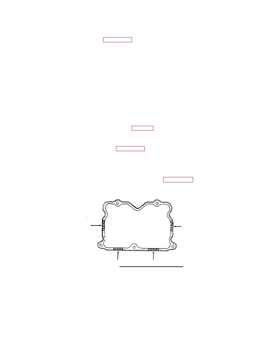
Stamped steel valve covers are designed and manufactured with 0.030 inch (0.75
mm) bow located in the shaded areas as shown in FIGURE 3-29 to provide better
sealing qualities. This built in bow on the valve covers must not be mistaken for
warpage. Also, do not attempt to increase or remove the bow from the sealing
surface.
FIGURE 3-29. Cover Manufactured Bow Areas .
q. Install the covers (5, 6, 7) on the rocker lever housings (14).
r. Install the five assembled washerscrews (4) in each cover.
3-43
|
||
|
||


