
| Tweet |

Custom Search
|
|

|
||
 TM 55-1905-223-24-5
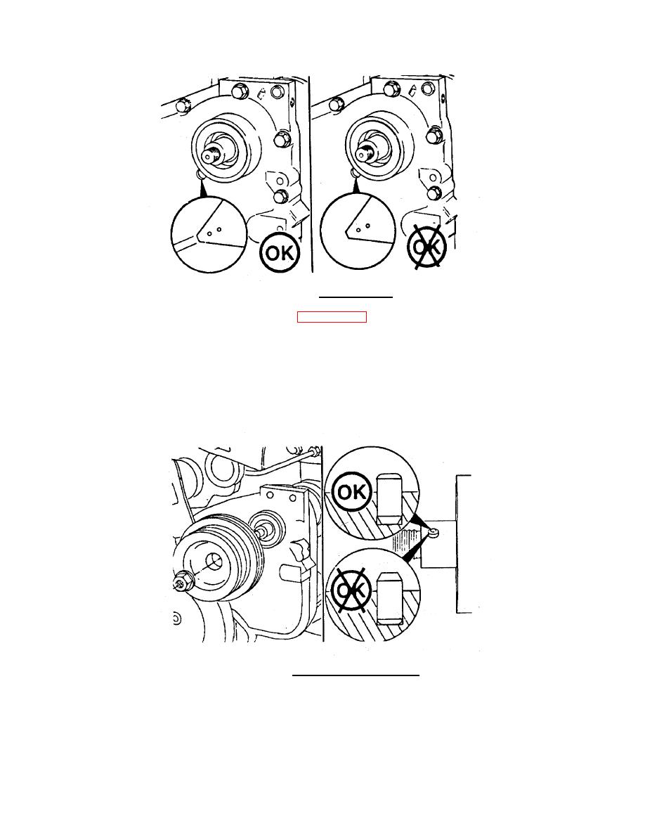
FIGURE 3-43. Gear Alignment.
h.
Remove self locking capscrew (1, FIGURE 3-40) from shaft (4) and washer (20).
i.
Remove gear (8), bushing (16) and thrust bearing (7) from shaft (4).
j.
Remove coupling (2), washer (19) and thrust bearing (3) from shaft (4).
k.
Pull shaft (4) with groove pin (18) from pulley end of accessory drive housing (17).
l.
Remove groove pin (18) from shaft (4).
FIGURE 3-44. Accessory Drive Dowel Pin.
3-64
|
||
|
||


