
| Tweet |

Custom Search
|
|

|
||
 TM 55-1905-223-24-5
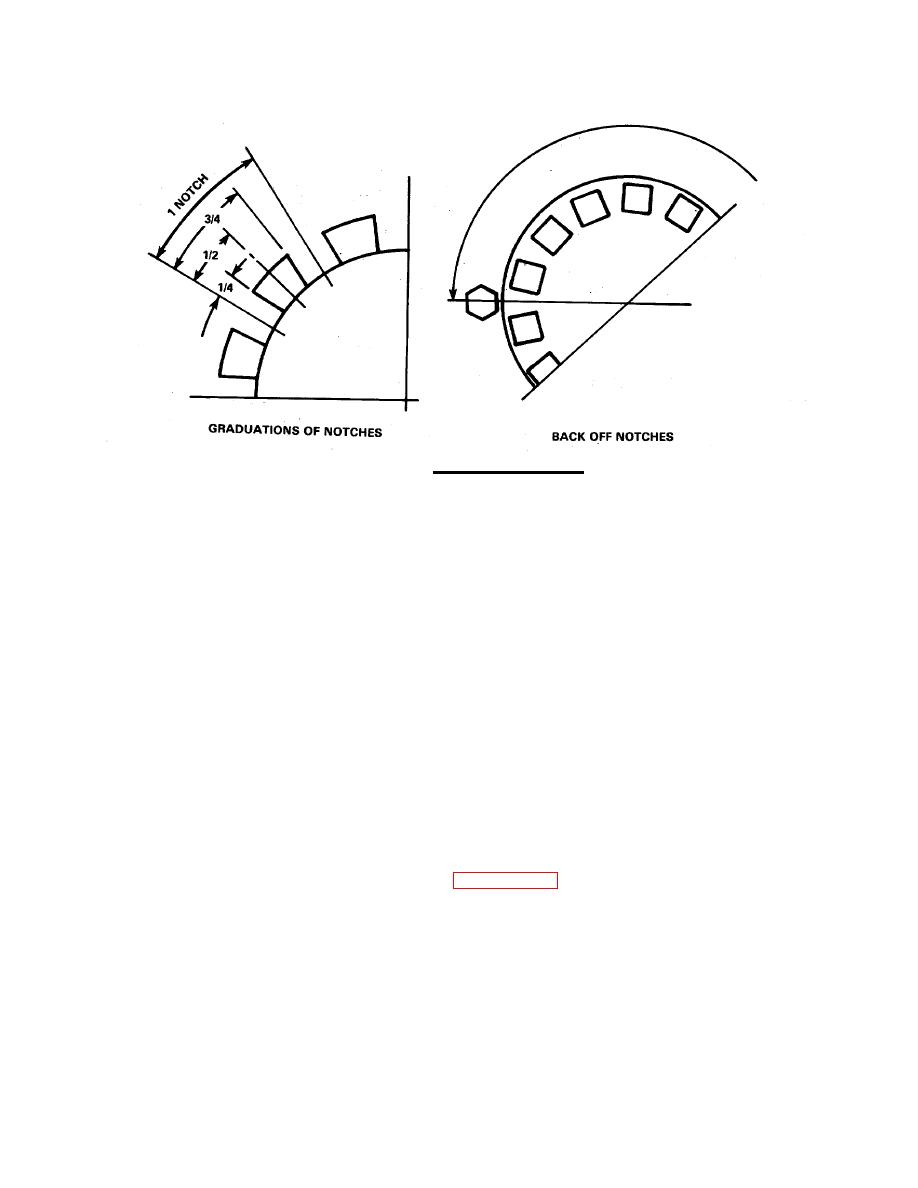
FIGURE 3-62. Adjusting Retainer Nut.
(2)
Attach an eyebolt in the 1/4 PTF thread at the output end of the shaft. (Models which do not
have this hole will have to inverted with the input end up, and clearance at the output end
below, for dial indicator mounting. An extra hub nut with a loop shaped strap welded to it can
be used to apply the pushing and pulling forces required during end play check.) See
FIGURE 3-61 .
(3)
Attach a dial indicator to the housing and locate the stem or plunger, from the indicator, on
the outer machined area of the end of the clutch .shaft. Mark a spot next to the indicator
stem.
(4)
Apply a pushing force of 200 pounds while turning the shaft two complete revolutions in each
direction (the weight of the shaft can be counted as part of the 200 pounds). With the
pushing force applied, stop the plunger or stem next to the mark and zero the dial indicator.
(5)
Apply a pulling force of 200 pounds (compensate for shaft weight) to the shaft and rotate,
with force applied two complete revolutions in each direction. Stop with force applied and
mark next to plunger or stem of the dial indicator. The indicator reads the actual end play.
(6)
Adjust nut to obtain the desired end play. Recheck final end play with the dial indicator as
described. Lock nut when end play adjustment is between 0.004 and 0.007 inch on the SL11
HP2 (0.006 to 0.010 on the SP 214 P2).
ac.
After adjustment, install the retainer lock (12, FIGURE 3-60, Sheet 1) and secure lock to the clutch
housing with a capscrew (10) and lock washer (11). Tighten the capscrew to 21-24 ft-lb torque. Be
sure to lubricate the main bearings through the housings fitting near the shaft exit.
3-96
|
||
|
||


