
| Tweet |

Custom Search
|
|

|
||
 TM 55-1905-223-24-5
FIGURE 3-66. Install the Guide Bushing into the Gear Pocket.
(2)
Install the dial indicator (3) into the setting block. Put the setting block on the setting standard
with the indicator tip on the diameter size of the bore to be cut. See Table 3-5. Adjust the dial
indicator.
(3)
Install the tool bit into the boring bar. Do not completely tighten the setscrew. Install the tool
bit adjusting knob into the boring bar. Hold the setting block and indicator against the boring
bar so the indicator tip will be over the tool bit. Turn the adjusting knob clockwise to push the
tool bit against the indicator tip. Adjust the tool bit until the indicator has the same reading as
when adjusted on the setting standard. After the tool bit is correctly adjusted, tighten the
setscrew and remove the adjusting knob.
(4)
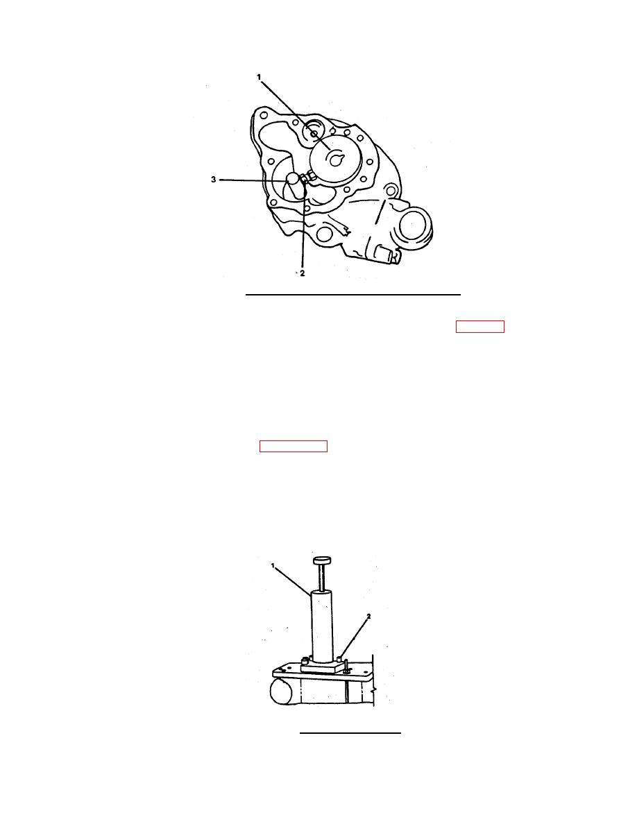
Install the boring tool (1, FIGURE 3-67) into the guide bushing. The tool bit must go through
the slot in the guide bushing. Do not hit the tool bit against the bushing.
(5)
Adjust the travel of the boring bar so the tool bit will go through the guide bushing but not
touch the bushing in the pump body.
(6)
Fasten the boring tool to the pump body with capscrews (2). Rotate the shaft to make sure it
will turn freely.
FIGURE 3-67. Install the Boring Tool.
3-104
|
||
|
||


