
| Tweet |

Custom Search
|
|

|
||
 TM 55-1905-223-24-5
NOTE
On PTO units which have been disassembled, steps (a)
through (i) of the Assembly Procedures must be
accomplished in order to reach a starting point for
bearing adjustment on the SP 111 HP2 (steps (a) through
(g) on the SP 214 P1, paragraph 4-15).
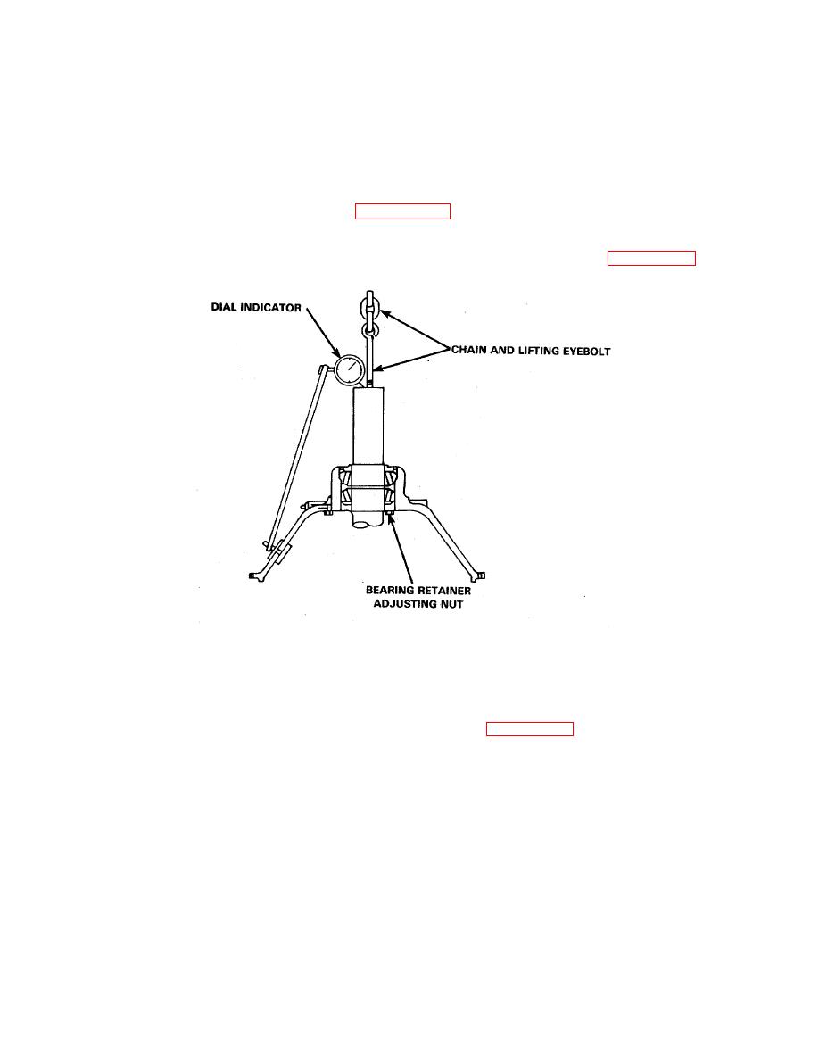
(1) Use the bearing retainer nut for adjusting the tapered roller bearings. Refer to FIGURE 4-22.
FIGURE 4-22. Adjusting Roller Bearings.
(a) Tighten the retainer nut until the shaft requires 60 in-lb. of force to turn.
(b) Back off the retainer nut 3-1/4-4-1/4 notches. See FIGURE 4-23.
(2) Dial indicate the end play as follows:
(a) Set PTO on supporting blocks with the clutch shaft in a vertical position with the input end
down.
(b) Attach an eyebolt in the 1/4 PTF thread at the output end of the shaft. (Models which do not
have this hole will have to be inverted with the input end up, and clearance-at the output end
below, for dial indicator mounting. An extra hub nut with a loop shaped strap welded to it car
be used to apply the pushing and pulling forces required-during end play check.) See
FIGURE 4-18.
4-46
|
||
|
||


