
| Tweet |

Custom Search
|
|

|
||
 TM 55-1905-242-14
OPERATOR, UNIT, DIRECT SUPPORT, AND GENERAL SUPPORT MAINTENANCE
FOR LANDING CRAFT, MECHANIZED (LCM-8) (ALL VESSELS WITH MOD 2 APPLICATION)
THEORY OF OPERATION
BILGE, OILY WATER, AND FIRE PUMP SYSTEMS
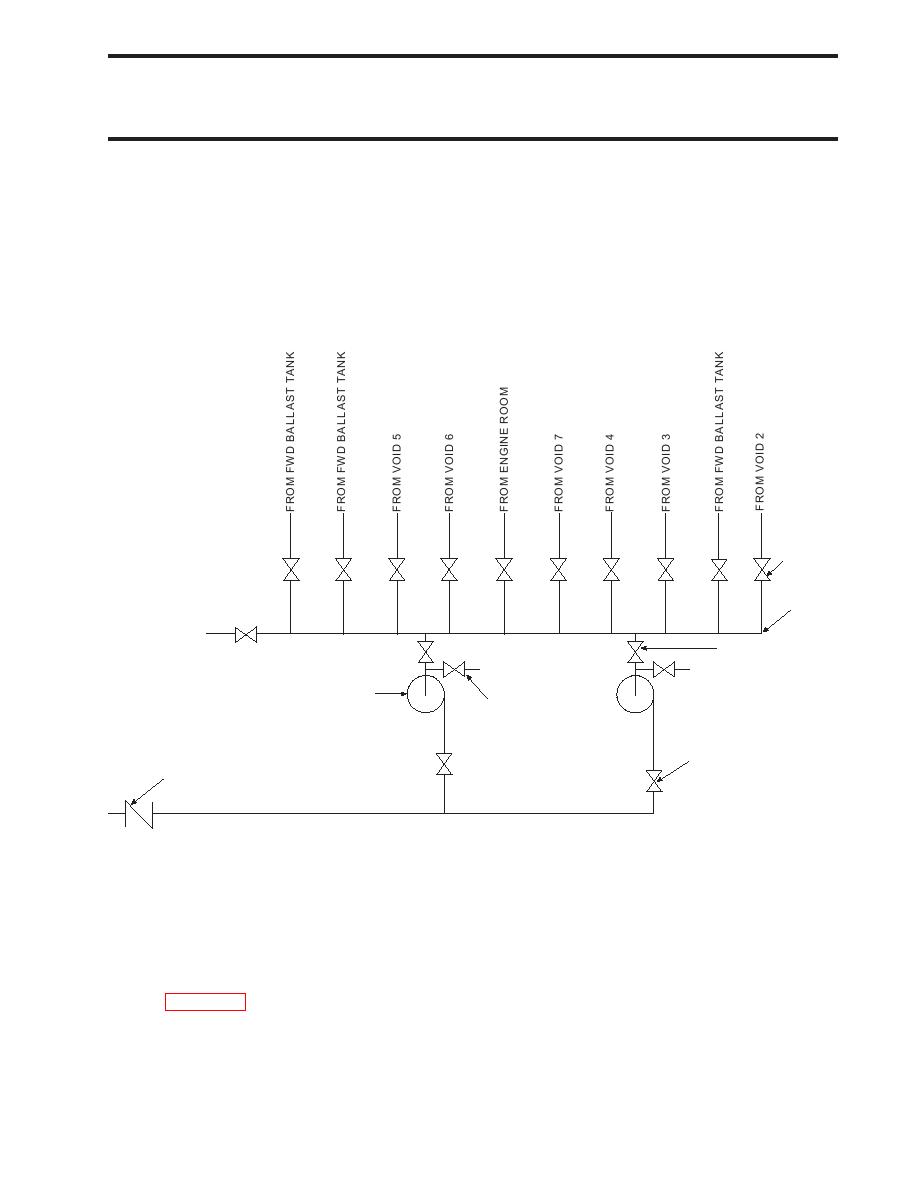
BILGE PUMPING SYSTEM
General
The bilge system provides the primary means for removing water from the watertight voids and spaces when flooding is
imminent aboard the LCM-8 Mod 2. Each watertight compartment aboard the LCM-8 Mod 2 has at least one bilge pump
suction point. The system consists of two hydraulically-driven bilge pumps, a bilge manifold, discharge valves, compart-
ment suction valves, pump suction valves, swing check valve, bilge strainers, and priming connectors. Discharge for this
system is directly overboard through the port side hull, aft of bulkhead 31.
COMPART-
MENT
SUCTION
VALVE
(TYP)
BILGE
MANIFOLD
TO OILY
WATER
PUMP
DISCHARGE
SUCTION
PUMP
VALVE (P/S)
BILGE PUMP (P/S)
PRIMING
CONNECTOR
(P/S)
PUMP DISCHARGE
VALVE (P/S)
SWING CHECK
VALVE
BILGE PUMPING SCHEMATIC
Bilge Pump
Two hydraulically-driven centrifugal bilge pumps, one port and one starboard, provide emergency bilge pumping capability
for the LCM-8 Mod 2. Both pumps are located in the engine room at frame 32 port and starboard of centerline. The pumps
are powered by hydraulic pumps contained in the bilge/ramp/crane hydraulic system. Operation of this hydraulic system is
detailed in WP 0006 00.
Bilge Manifold
A single bilge manifold, located aft of bulkhead 31 centerline, is used to connect the bilge pumps with the various bilge
strainers. By properly aligning the valves at the bilge manifold, the operator can pump bilge from any of the watertight
compartments.
0007 00-1
|
||
|
||


