
| Tweet |

Custom Search
|
|

|
||
 TM 55-1905-242-14
0063 00
REMOVAL (continued)
! CAUTION
Wiring is connected to the rear of the face plate assembly. Take care when removing the
face plate assembly. Wiring damage can result from rough handling during removal.
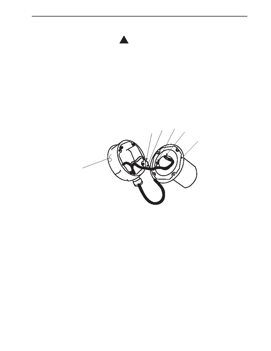
5.
Remove the four screws (5) that secure the face plate assembly (6) to the junction box (7). Pull the face plate assembly
away from the junction box, taking care not to damage the wiring behind the face plate assembly.
6.
Set the multimeter to the Vdc (Volts direct current) setting. Place one multimeter lead on each of the wiring terminals (8)
on the rear of the face plate assembly (6). If no voltage is noted, proceed to the next step. If voltage is noted, ensure that
the proper circuit breaker is properly secured.
7.
Label and disconect the wiring (9) from the terminals (8) on the rear of the face plate assembly (6).
8
9
8
9
6
7
INSTALLATION
1.
Connect the wiring (9) to the terminals (8) on the rear of the face plate assembly (6) using the labels from step 7 of
Removal--Lighting Fixture, Incandescent as a guide.
2.
Position the face plate assembly (6) on the junction box (7) and secure it with the four screws (5).
3.
Screw the light bulb (3) into the socket (4).
4.
Screw the globe (2) onto the face plate assembly (6).
5.
Screw the guard (1) onto the face plate assembly (6).
6.
Remove the lockouts and tagouts and check the operation of the light.
0063 00-3
|
||
|
||


