
| Tweet |

Custom Search
|
|

|
||
 TM 55-1905-242-14
0086 00
REMOVAL (continued)
NOTE
Cotter pins, lockwashers, locking nuts, and similar locking devices shall be discarded after removal and replaced with
new cotter pins, lockwashers, locking nuts and similar locking devices.
5.
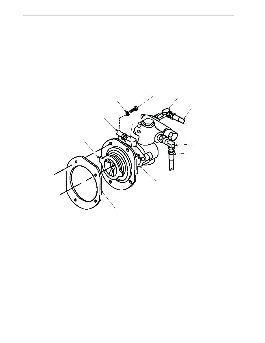
Remove the bolts (4) and lockwashers (5) that secure the pump (6) to the engine.
6.
Remove the pump (6) and gasket (7). Discard the gasket.
7.
Label and remove all three elbows (8) from the pump (6).
8.
Carefully clean any remaining gasket material from the engine mounting surface.
4
8
5
1
3
8
9
8
2
6
7
INSTALLATION
1.
Position the pump (6) and new gasket (7) in place on the engine, ensuring that the pump's drive tangs (9) are aligned with
the engine's drive slots.
2.
Secure the pump (6) to the engine using the bolts (4) and lockwashers (5).
3.
Install the three elbows (8) onto the pump (6) using the labels from step 7 of Removal as a guide.
4.
Uncap the hoses (1, 2, and 3) one at a time, and install them on their respective elbows (8).
5.
Check the hydraulic fluid level in the reservoir and replenish it as required.
6.
Remove the lockouts and tagouts and check the operation of the system. Also check for any leaks.
7.
After checking the system operation, secure the engine and recheck the hydraulic fluid level. Replenish it as required.
8.
Dispose of used hydraulic fluid, cleaning solvent, and contaminated materials in accordance with local regulations.
END OF WORK PACKAGE
0086 00-2
|
||
|
||


