
| Tweet |

Custom Search
|
|

|
||
 TM 55-1905-242-14
0088 00
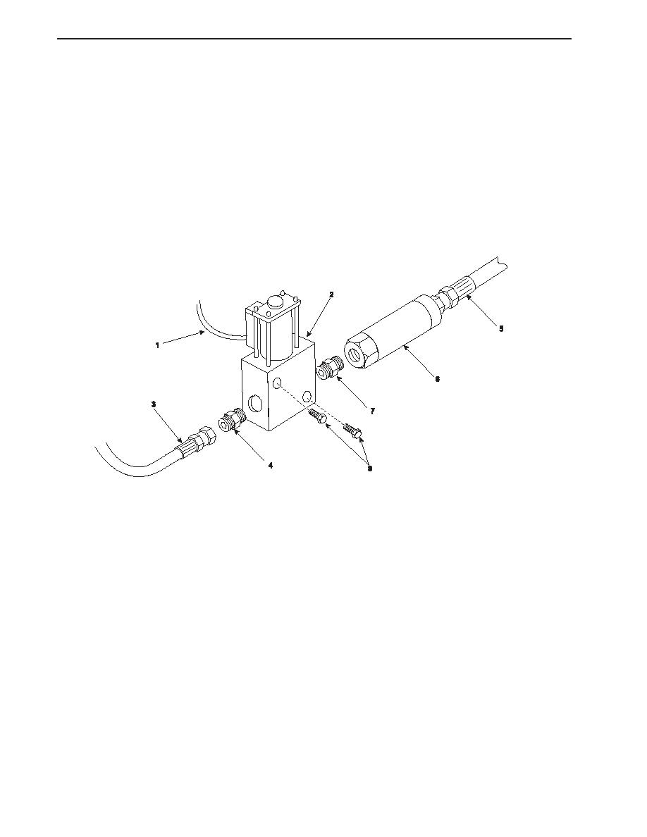
REMOVAL (continued)
4.
Position a suitable drain pan beneath the control valve (2).
5.
Label and remove the outlet hose (3) from the outlet fitting (4). Cap the hose to prevent system contamination.
6.
Remove the outlet fitting (4) from the control valve (2).
7.
Label and remove the inlet hose (5) from the filter (6). Cap the hose to prevent system contamination.
8.
Remove the filter (6) from the inlet fitting (7).
9.
Remove the inlet fitting (7) from the control valve (2).
10. Remove the two bolts (8) that secure the control valve (2) to its bracket.
INSTALLATION
1
Position the control valve (2) on its bracket and secure it with the two bolts (8).
2.
Wrap the male pipe threads with antiseizing sealant tape and install the inlet fitting (7) and the outlet fitting (4) into the
control valve (2).
3.
Install the filter (6) onto the inlet fitting (7).
4.
Install the inlet hose (5) onto the filter (6) using the label from step 7 of Removal as a guide.
5.
Install the outlet hose (3) onto the outlet fitting (4) using the label from step 5 of Removal as a guide.
6.
Connect the electrical leads (1) to the control valve (2) using the labels from step 2 of Removal as a guide.
7.
Remove the lockouts and tagouts, charge the system, and check the system operation. Also check for any sign of
leakage.
8.
Check the hydraulic fluid level in the reservoir and replenish it as necessary.
9.
Dispose of used hydraulic fluid and contaminated materials in accordance with local regulations.
END OF WORK PACKAGE
0088 00-2
|
||
|
||


