
| Tweet |

Custom Search
|
|

|
||
 TM 55-1905-242-14
0090 00
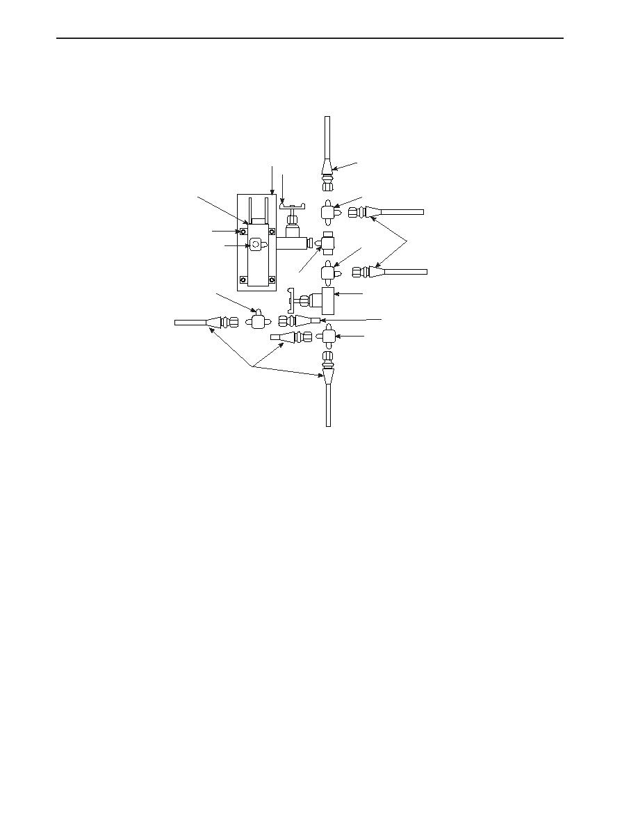
REMOVAL (continued)
5.
Label all tees (2 and 4), valves (3 and 5), and elbow (6), and remove them from the pump (9).
10
1
5
9
2
7,8
1
6
2
4
2
3
1
2
1
NOTE
Cotter pins, lockwashers, locking nuts, and similar locking devices shall be discarded after removal and replaced with
new cotter pins, lockwashers, locking nuts and similar locking devices.
6. Remove the bolts (7) and lockwashers (8) that secure the pump (9) to its foundation (10), and lift the pump
from its foundation.
INSTALLATION
1.
Secure the pump (9) to its foundation (10) using the bolts (7) and lockwashers (8).
2.
Install the tees (2 and 4), valves (3 and 5), and elbow (6) to their original configuration using the labels from step 5 of
Removal as a guide.
3.
Connect the hydraulic lines (1) to their original configuration using the labels from step 4 of Removal as a guide.
4.
Remove the lockouts and tagouts and check the operation of the pump, ensuring that it will charge the accumulators and
that no leakage is present.
5.
Check the level of hydraulic fluid in the reservoir and replenish the hydraulic fluid as required.
6.
Dispose of used hydraulic fluid, cleaning solvent, and contaminated materials in accordance with local regulations.
END OF WORK PACKAGE
0090 00-2
|
||
|
||


