
| Tweet |

Custom Search
|
|

|
||
 TM 55-1905-242-14
0105 00
INSTALLATION (continued)
! CAUTION
Do not overtighten the nuts that secure the remote display to the console. Overtighten-
ing the nuts can distort the remote display causing damage to the unit. Sealing com-
pound should be used during installation to prevent future loosening of the nuts.
d.
Apply a small amount of sealing compound (Loctite 242) to the studs and install the nuts (8) and washers (9).
Tighten the nuts only lightly to prevent distortion of the remote display unit (7).
3.
To install the junction box:
a.
Position the junction box (6) on the console and secure it with the screws (14) and washers (15).
b.
Connect the remote display unit cable (10), the processor unit cable (4), and the power cable (12) to their sockets (11,
5, and 13) on the junction box (6).
4.
After installing all of the components, clear the lockouts and tagouts and test the operation of the system as follows:
a.
Set to ON the POWER toggle switch and observe the remote display unit (7). The remote display should show the
default declination value (00) for two seconds, and then change to Compass Heading mode.
b.
Set to the LIGHT ON position the POWER toggle switch. Rotate the DIMMER control and observe that the lighting
varies between OFF and full brightness.
c.
Proceed to the Calibration procedure in this work package and calibrate the unit.
CALIBRATION
During calibration, the vessel is steered through two slow, continuous circles while the digital compass conducts its
calibration routine. As the vessel turns through the circles, the remote display unit shows sequential displays of "CAL," the
present heading, and a three digit calibration score. The three digit score indicates the quality of the calibration (on a scale
of 1 to 9, with 1 being the worst and 9 being the best), the quality of the local magnetic environment (using the same scoring
method), and the number of calibrations conducted (the third digit is a rollover counter that increments by one with each
calibration). To calibrate the unit:
1.
Position the vessel in an area large enough to conduct two large, slow circles over a period of several minutes. Each full
circle requires at least two minutes to complete (i.e. the turn rate should not exceed three degrees per second). The
starting heading is not important, nor is the direction of the turn.
2.
Set to ON the POWER toggle switch and allow the digital compass to go through its self-test routine.
3.
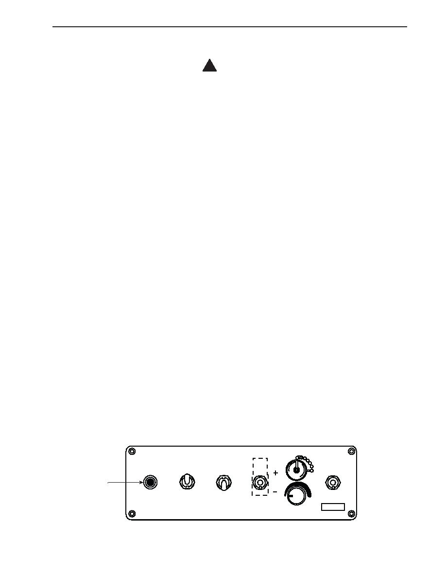
When ready to begin calibration, steady on any heading, then press and hold down the SET CRS pushbutton (16) for
approximately eight seconds, or until the remote display unit shows "CAL." Release the SET CRS pushbutton.
MV103 DIGITAL COMPASS
3/10A SB
KHV INDUSTRIES MIDDLETOWN RI USA
F1
LIGHT
CAL (HOLD DOWN)
SLOW
ON
EAST
16
MED
ON
FAST
WEST
OFF
GPS/
SET
POWER
DECL
NAV
CRS
RESPONSE
DIMMER
0105 00-3
|
||
|
||


