
| Tweet |

Custom Search
|
|

|
||
 TM 55-1905-242-14
0106 00
4
5
1
1
3
5
2
4
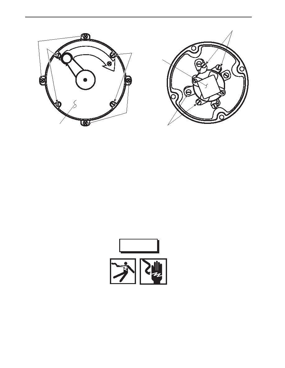
INSTALLATION
1.
Align the contactor switch assembly to the mounting bracket, and secure it in place with the four screws (5).
2.
Connect the electrical wiring to the terminals (4) on the contactor switch (3) using the labels from step 4 of Removal--
Contactor Switch Assembly as a guide.
3.
Install the contactor switch cover (2) and secure it in place with the four screws (1).
4.
Remove the lockouts and tagouts and check the operation of the system.
ALARM BELL REPLACEMENT
REMOVAL
WARNING
Replace or repair components only after the affected circuit has been secured, locked
out, and tagged out. Performing replacement with the circuit energized may result in
damaged equipment and serious injury or death to personnel.
1.
Remove the bolt (6) that secures the gong (7) to the base (8), and remove the gong.
2.
Remove the bolts (behind the gong) that secure the cover to the base (8).
0106 00-2
|
||
|
||


