
| Tweet |

Custom Search
|
|

|
||
 TM 55-1905-242-14
0106 00
REMOVAL (continued)
3.
Set the multimeter to the Vdc (Volts direct current) setting. Take voltage readings at the terminals, inside the base (8), to
ground to ensure that the electrical circuits are deenergized. If no voltage is noted, proceed to the next step. If voltage
is noted, ensure that the affected circuit breaker is properly secured.
4.
Label and remove the wiring from the terminals inside the base (8).
5.
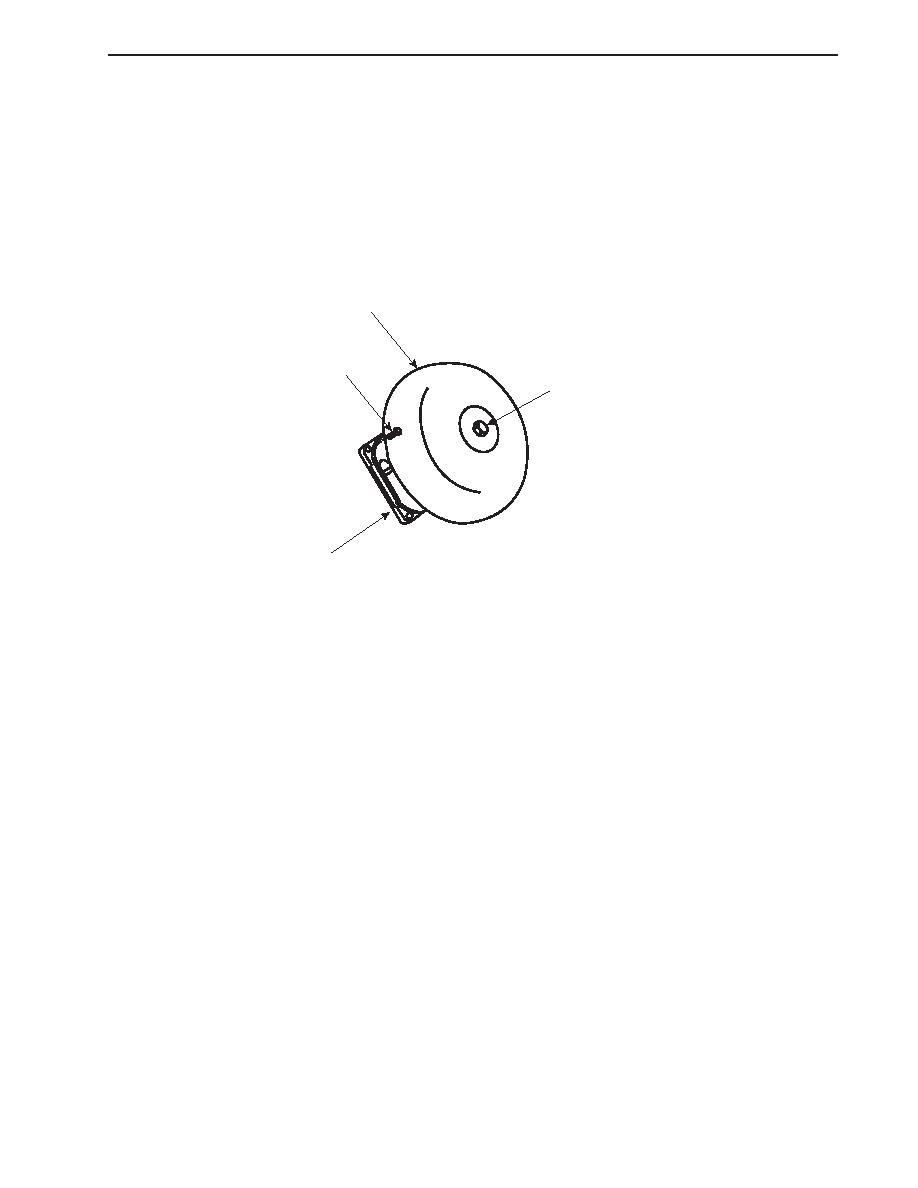
Remove the four bolts (9) that secure the base (8) to the bulkhead.
7
9
6
8
INSTALLATION
1.
Position the base (8) against the bulkhead and secure it with four bolts (9).
2.
Connect the wiring inside the base (8) using the labels from step 4 of Removal--Alarm Bell Replacement as a guide.
3.
Attach the cover to the base (8) with its bolts.
4.
Secure the gong (7) to the base (8) with the bolt (6).
5.
Remove the lockouts and tagouts and check the operation of the system.
END OF WORK PACKAGE
01060106 00-3
00-3/4 blank
|
||
|
||


