
| Tweet |

Custom Search
|
|

|
||
 TM 55-1905-242-14
0121 00
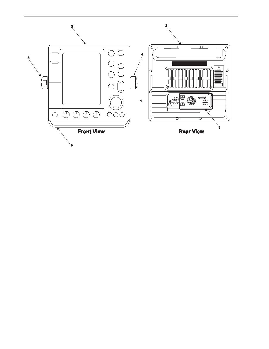
INSTALLATION--DISPLAY
1.
Place the display (2) in its mount (5) and secure it with the two knobs (4).
2.
Connect the wiring to the terminals (1 and 3) at the rear of the display (2) using the labels from steps 1and 2 of Removal-
-Display as a guide.
3.
Remove the lockouts and tagouts and check the operation of the system.
REMOVAL--ARRAY ASSEMBLY
NOTE
Cotter pins, lockwashers, locking nuts, and similar locking devices shall be discarded after removal and replaced with
new cotter pins, lockwashers, locking nuts and similar locking devices.
1.
Remove the nuts (6), lockwashers (7), and flat washers (8) from the studs (9) that secure the array (10) to the pedestal (11).
2.
Carefully lift the array (10) straight up and away from the pedestal (11), taking care that the coaxial mounting pin (12) is
not damaged during removal.
3.
Loosen the four self-retaining bolts (13) securing the pedestal lid (14) to the pedestal base (15). Pull each self-retaining
bolt up and turn it counterclockwise to lock it in the upright position.
4.
Open the pedestal lid (14), ensuring that the securing stay has automatically locked into position.
5.
Set the multimeter to the Vdc (Volts direct current) setting, and check for voltage across the positive (16) and negative
(17) terminals of the power connector (18). If no voltage is noted, proceed to the next step. If voltage is noted, ensure
that the circuit breaker is properly secured.
6.
Label and disconnect the wiring from the positive (16) and negative (17) terminals of the power connector (18). Discon-
nection is accomplished by pressing the locking tabs (19) with a screwdriver (20) to free the connection.
7.
Disconnect the signal connector (21).
0121 00-2
|
||
|
||


