
| Tweet |

Custom Search
|
|

|
||
 TM 55-1905-242-14
0136 00
INSTALLATION--TANK UNIT (continued)
4.
Fill the black water tank with fresh water and check for leaks at the tank unit (3).
5.
Remove the lockouts and tagouts and check the operation of the system.
6.
Install the void cover on Void 6, pump out the black water tank, and terminate the enclosed space procedures.
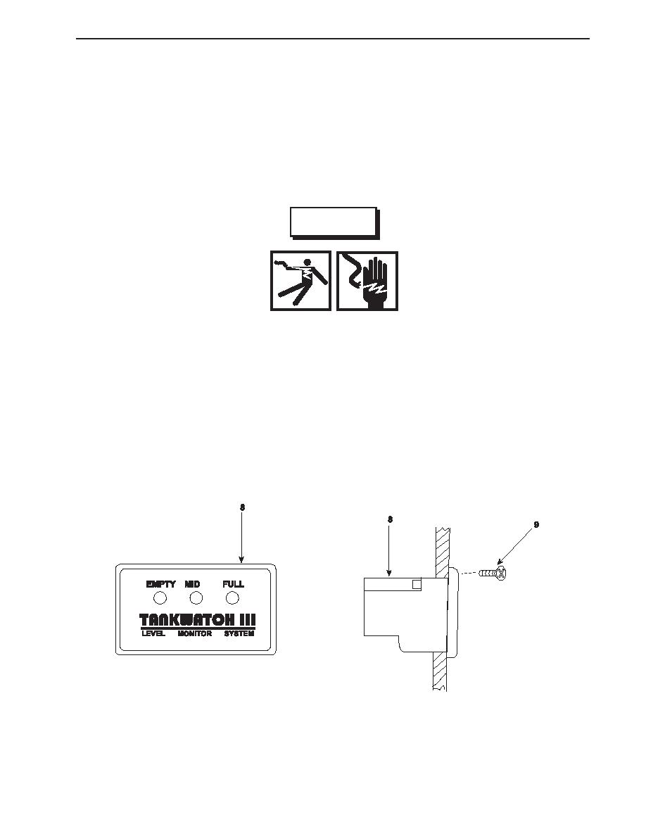
REMOVAL--DISPLAY UNIT
1.
Remove the lower starboard panel from the console.
WARNING
Replace or repair components only after the affected circuit has been secured, locked
out and tagged out. Performing replacement with the circuit energized may result in
damaged equipment and serious injury or death to personnel.
2.
Set the multimeter to the Vdc (Volts direct current) setting. Place the positive multimeter lead on terminal #2 on the back
of the display unit (8) and the negative lead on the #4 terminal on the back of the display unit. If no voltage is noted,
proceed to the next step. If voltage is noted, ensure that the circuit breaker is properly secured.
3.
Label and remove the wiring from the back of the display unit (8).
4.
Remove the four screws (9) that secure the display unit (8) to the panel.
0136 00-3
|
||
|
||


