
| Tweet |

Custom Search
|
|

|
||
 TM 55-1905-242-14
0145 00
ALIGN (continued)
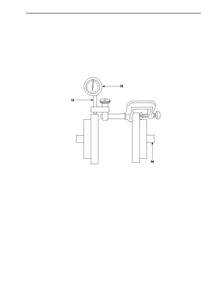
11. Reposition the dial indicator (12) as shown to check the parallel alignment. The dial indicator should have a 0.200 inch
to 0.300 inch preload when installed against the engine flange.
12. Zero the dial indicator (12) by twisting its bezel (13).
13. Slowly rotate the pump shaft (14) while noting the dial indicator (12) reading. Note how far the dial indicator needle
moves to either side of zero. Add the readings on both sides of zero to determine the amount of parallel misalignment.
For example, if the dial indicator needle moves 0.002 inch to one side of zero and 0.004 inch to the other side of zero, add
the two readings (0.002 in + 0.004 in = 0.006 in) to determine that the parallel misalignment is 0.006 inch.
14. Maximum parallel misalignment is 0.150 inch (3.80 mm). If the parallel misalignment exceeds this specification, the
misalignment must be corrected. Parallel misalignment is corrected by loosening the pump mounting bolts, fabricating
shims from shim stock, and placing the shims between the pump mounting pads and the pump mounts. After adjusting
the alignment, tighten the pump mounting bolts and recheck the alignment.
15. It is frequently necessary to adjust both the angular and the parallel alignment several times before the correct alignment
is obtained. Once the proper angular and parallel alignment measurements are obtained, retighten the mounting bolts
one last time and recheck the measurement.
16. Once the final alignment has been obtained and rechecked, install the pump drive shaft (2) and secure it in place with the
six bolts (1).
17. Install the fire pump drive shaft guard.
18. Remove the lockouts and tagouts and check the operation of the fire pump, watching for any unusual noise or vibration.
END OF WORK PACKAGE
0145 00-3/4 blank
0145 00-3
|
||
|
||


