
| Tweet |

Custom Search
|
|

|
||
 TM 55-1905-242-14
UNITMAINTENANCE
FOR LANDING CRAFT, MECHANIZED (LCM-8) (ALL VESSELS WITH MOD 2 APPLICATION)
FIRE MONITOR, REPLACE/REPAIR
INITIAL SETUP:
Materials/Parts (continued):
Tools and Special Tools:
Goggles, Industrial, No Vents (Item 4, Table 2,
Tool Kit, Mechanic's Rail and Marine (Item 1,
Table 1, WP 0230 00)
Rag, Wiping (Item 5, Table 2, WP 0230 00)
Equipment Condition:
Petrolatum (Item 7, Table 2, WP 0230 00)
Sealing Compound, Loctite 242 (Item 16, Table 2,
Diesel generator, secured, locked out, and tagged
out IAW FM 55-502
Grease (Item 21, Table 2, WP 0230 00)
Personnel Required:
O-Ring (p/n 7-57-035, qty 3)
O-Ring (p/n 7-57-080, qty 1)
Two Watercraft Engineers, 88L
Gasket, Flange (p/n A-A-1719, 3", qty 1)
Materials/Parts:
References:
Cleaning Solvent MIL-PRF-680 (Item 2, Table 2,
FM 55-502
TM 55-1905-242-24P (WP 0072)
Gloves, Chemical Protective (Item 3, Table 2,
REMOVAL
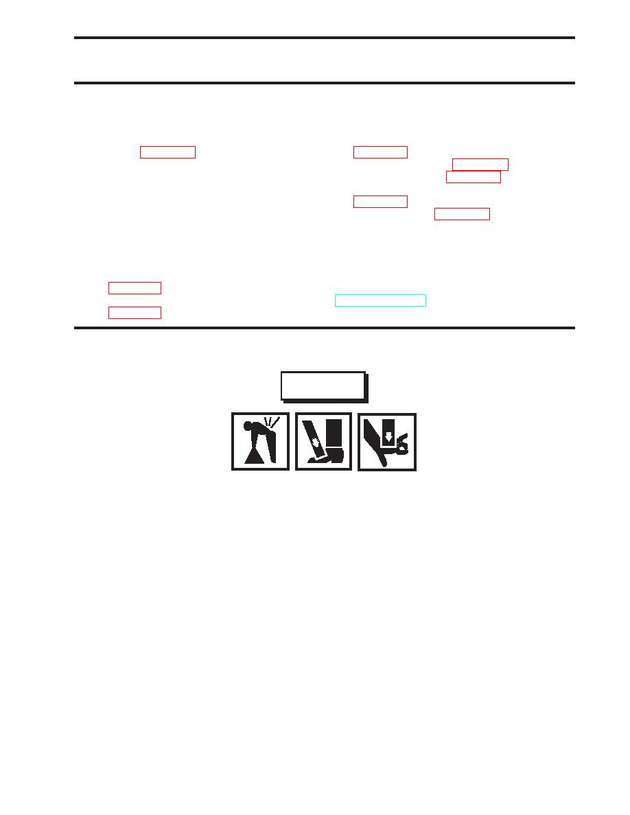
WARNING
Use two crewmembers to lift heavy loads. Heavy loads can crush. Do not allow any
body parts to come under the load or between the load and a stationary object. Failure
to comply can result in serious injury or death.
1.
Attach a safety line to the fire monitor to prevent loss overboard.
2.
Remove the bolts (1) that secure the fire monitor flange base (2) to its mount.
3.
Using two crewmembers, remove the fire monitor assembly from its mount.
DISASSEMBLY
NOTE
The upper and lower friction screws are not interchangeable. Tag these screws during
Disassembly to ensure that they are installed in the proper locations during Assembly.
1.
Remove the set screw (3) that retains the upper friction screw (4) and remove the upper friction screw. Tag the upper
friction screw to ensure that it is installed in the proper location during Assembly.
2.
Remove the swivel plugs (5) from the outlet elbow (6).
0147 00-1
|
||
|
||


