
| Tweet |

Custom Search
|
|

|
||
 TM 55-1905-242-14
0147 00
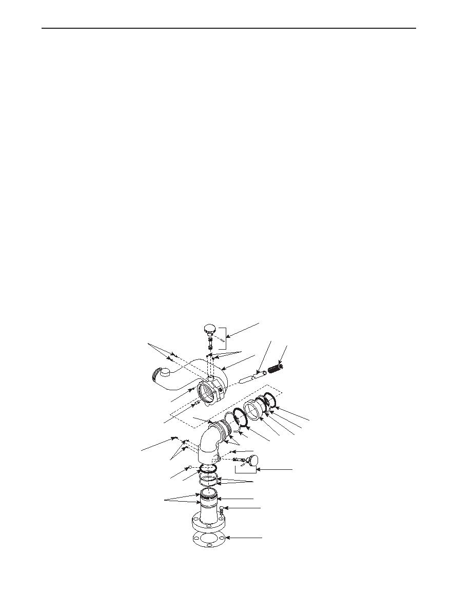
DISASSEMBLY (continued)
NOTE
The joint between the outlet elbow and the elbow is supported by ball bearings. These
ball bearings are easily lost during Disassembly. In order to prevent the loss of ball
bearings, place several wiping rags under the joint during Disassembly.
3.
Position several wiping rags under the joint between the outlet elbow (6) and the elbow (7). Turn the outlet elbow to
permit the outer (8) and inner (9) ball bearings to fall from the swivel plug (5) holes. It may be necessary to insert a length
of flexible wire into the swivel plug holes to coax the ball bearings out.
4.
Count and record the number of outer (8) and inner (9) ball bearings that were removed from the joint. There are normally
56 outer ball bearings and 45 inner ball bearings, but this number can vary.
5.
Use a twisting, pulling motion to separate the outlet elbow (6) from the elbow (7). If the components do not come apart
easily, repeat step 3 to ensure that all of the outer (8) and inner (9) ball bearings have been removed from the joint.
NOTE
The upper and lower friction screws are not interchangeable. Tag these screws during
Disassembly to ensure that they are installed in the proper locations during Assembly.
6.
Remove the set screw (10) that retains the lower friction screw (11) and brake ball (12) and remove the friction screw. Tag
the lower friction screw to ensure that it is installed in the proper location during Assembly.
7.
Remove the swivel plugs (13) from the elbow (7).
4
19
15
20
5
6
3
7
16
21
9
16
18
8
17
24
10
15
13
11
12 16
14
2
23
1
22
0147 00-2
|
||
|
||


