
| Tweet |

Custom Search
|
|

|
||
 TM 55-1905-242-14
0171 00
DISASSEMBLY (continued)
k.
Remove the shaft (25) and the bearings (26) from the pedestal (10) as an assembly. Do not remove the bearings from
the shaft unless they must be replaced. If the bearings must be replaced, use a puller to pull them off the shaft.
4.
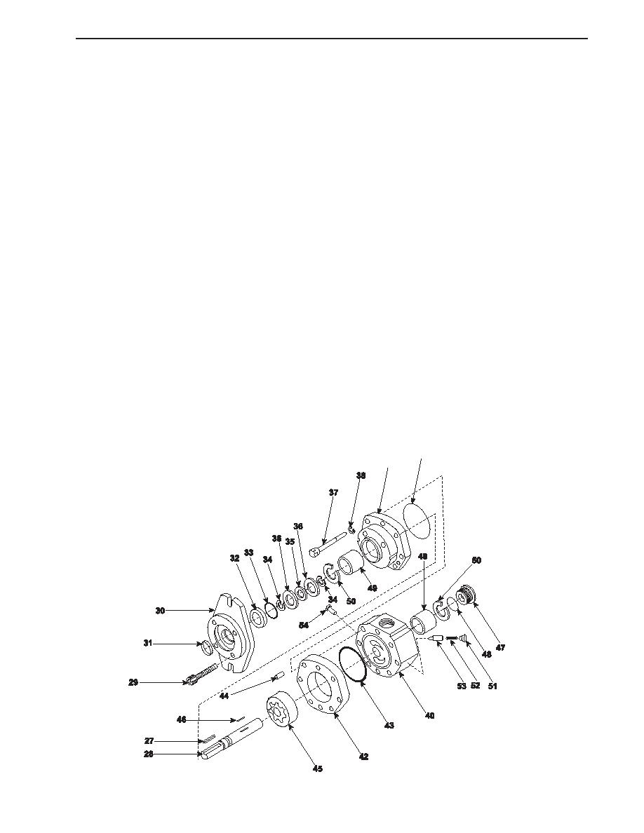
To disassemble the hydraulic motor:
a.
Remove the shaft drive key (27) from the shaft (28).
b.
Remove the four screws (29) from the face of the mounting flange (30). Remove the mounting flange.
c.
Remove the shaft dirt seal (31), high pressure shaft seal (32), O-ring (33), retainer rings (34), thrust bearing (35), and
washers (36).
d.
Remove the six screws (37) and lockwashers (38) that secure the front bearing housing (39) to the motor body (40).
e.
Separate the front bearing housing (39) from the motor body (40). Remove the motor body and front bearing
housing O-ring (41).
f.
Remove the gerotor housing (42) and O-ring (43) from the motor body (40). Do not remove the four locating dowels
(44) unless they must be replaced.
g.
Remove the gerotor (45) and the gerotor drive key (46) from the shaft (28).
h.
Remove the end plug (47) and O-ring (48) from the motor body (40).
i.
Do not remove the roller bearings (49) from the motor body (40) or from the front bearing housing (39) unless the
bearings will be replaced. If the bearings will be replaced, remove the retaining rings (50) from the motor body
and front bearing housing and gently drive out the bearings.
41
39
0171 00-3
|
||
|
||


