
| Tweet |

Custom Search
|
|

|
||
 TM 55-1905-242-14
0185 00
REMOVAL (continued)
INSTALLATION
1.
If the coupling is being replaced, to install it:
a.
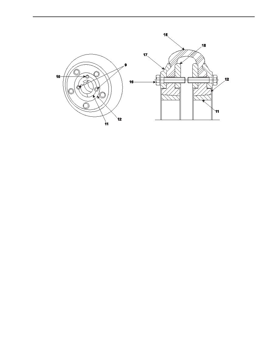
Position the coupling (15) on the first side of the side flange (12).
b.
Position the inner (18) and outer (17) clamp rings and secure them loosely with the clamp bolts (16). Tighten the
bolts only finger tight at this point.
c.
Position the remaining side flange (12) in the coupling (15).
d.
Position the inner (18) and outer (17) clamp rings and secure them loosely with the clamp bolts (16). Tighten the
bolts only finger tight at this point.
e.
Check all around the coupling assembly to ensure that the coupling (15) is properly seated in the side flange (12) and
inner (18) and outer (17) clamp rings.
f.
Tighten all of the clamp bolts (16).
2.
Place the taper lock (11) over the pump (7) shaft with the fixing holes facing the pump.
3.
Position the pump (7) in its mounting bracket (14) and secure it with the bolts (13).
4.
Connect the piping (6) to the pump (7) with the bolts (5).
5.
To connect the coupling to the pump:
a.
Align the fixing holes on the taper lock (11) with the fixing holes on the side flange (12).
b.
Slide the taper lock (11) into the side flange (12) and secure it with the socket head fixing bolts (9).
NOTE
Cotter pins, lockwashers, locking nuts, and similar locking devices shall be discarded
after removal and replaced with new cotter pins, lockwashers, locking nuts and similar
locking devices.
6.
Position the guard (4) on the structure and secure it with the bolts (1), nuts (2), and lockwashers (3).
0185 00-3
|
||
|
||


