
| Tweet |

Custom Search
|
|

|
||
 TM 55-1905-242-14
0191 00
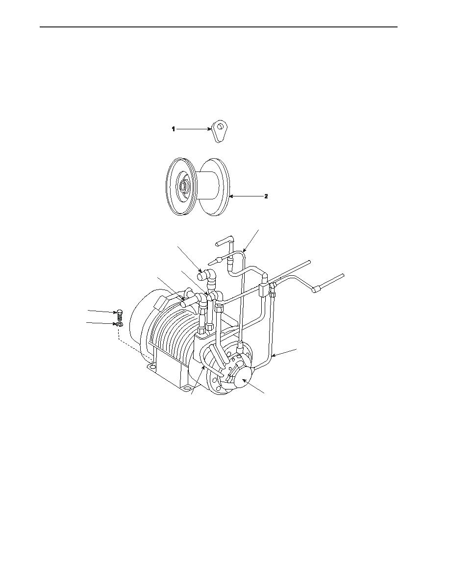
REMOVAL (continued)
NOTE
Cotter pins, lockwashers, locking nuts, and similar locking devices shall be discarded after removal and replaced with
new cotter pins, lockwashers, locking nuts and similar locking devices.
8.
Remove the mounting bolts (10) and lockwashers (11) that secure the winch (8) to its foundation.
9.
Attach a suitable hoisting device to the winch (8) and remove it from its foundation.
9
5
4
3
10
11
7
INSTALLATION
8
6
1.
Ensure that the final drive is filled with gear lubricating oil 80W-90 to the level of the filler plug.
2.
Fill the primary drive assembly with hydraulic fluid through the vent port (Q).
3.
Use a suitable hoisting device to set the winch (8) on it foundation.
4.
Secure the winch (8) to its foundation with the mounting bolts (10) and lockwashers (11).
5.
Remove the caps and connect the hoses (3, 4, 5, 6, and 7) to the winch (8) using the labels from step 6 of Removal as a
guide.
6.
Remove the caps and connect the tubing (9) to the winch (8).
7.
To check the alignment of the winch:
a. Use feeler gauges to measure the clearance between the winch drum and the final drive (Y) at points "V" and "W."
b.
Use feeler gauges to measure the clearance between the winch drum and the primary drive (Z) at points "V" and "W."
0191 00-2
|
||
|
||


