
| Tweet |

Custom Search
|
|

|
||
 TM 55-1905-242-14
0192 00
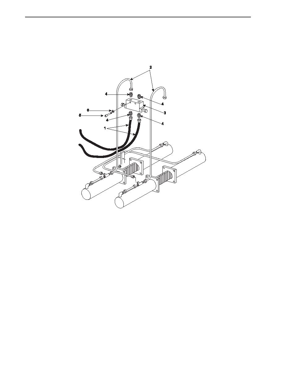
REMOVAL--SLEWING STOP VALVE (continued)
NOTE
Cotter pins, lockwashers, locking nuts, and similar locking devices shall be discarded after removal and replaced with
new cotter pins, lockwashers, locking nuts and similar locking devices.
5.
Remove the bolts (5) and lockwashers (6) that secure the slewing stop valve (3) to the structure. Remove the slewing
stop valve.
INSTALLATION--SLEWING STOP VALVE
1.
Position the slewing stop valve (3) on the structure and secure it with the bolts (5) and lockwashers (6).
2.
Install the fittings (4) into the slewing stop valve (3) using the labels from step 4 of Removal--Slewing Stop Valve as a
guide.
3.
Install the hoses (1) and piping (2) onto the slewing stop valve (3) using the labels from step 3 of Removal--Slewing Stop
Valve as a guide.
4.
If no further work will be performed, remove the lockouts and tagouts and check the operation of the system.
a.
Slew the boom from one extreme to the other and ensure that the slewing stop valve stops the boom from slewing
at both extremes of swing.
b.
Check that the boom slews smoothly at both slow and fast speeds.
c.
Check that the boom stops properly when the control is released.
d.
Check that no leaks are present.
5.
Dispose of used hydraulic fluid and contaminated materials in accordance with local regulations.
6.
Check the hydraulic fluid level in the reservoir and replenish as required.
0192 00-2
|
||
|
||


