
| Tweet |

Custom Search
|
|

|
||
 TM 55-1905-242-14
0196 00
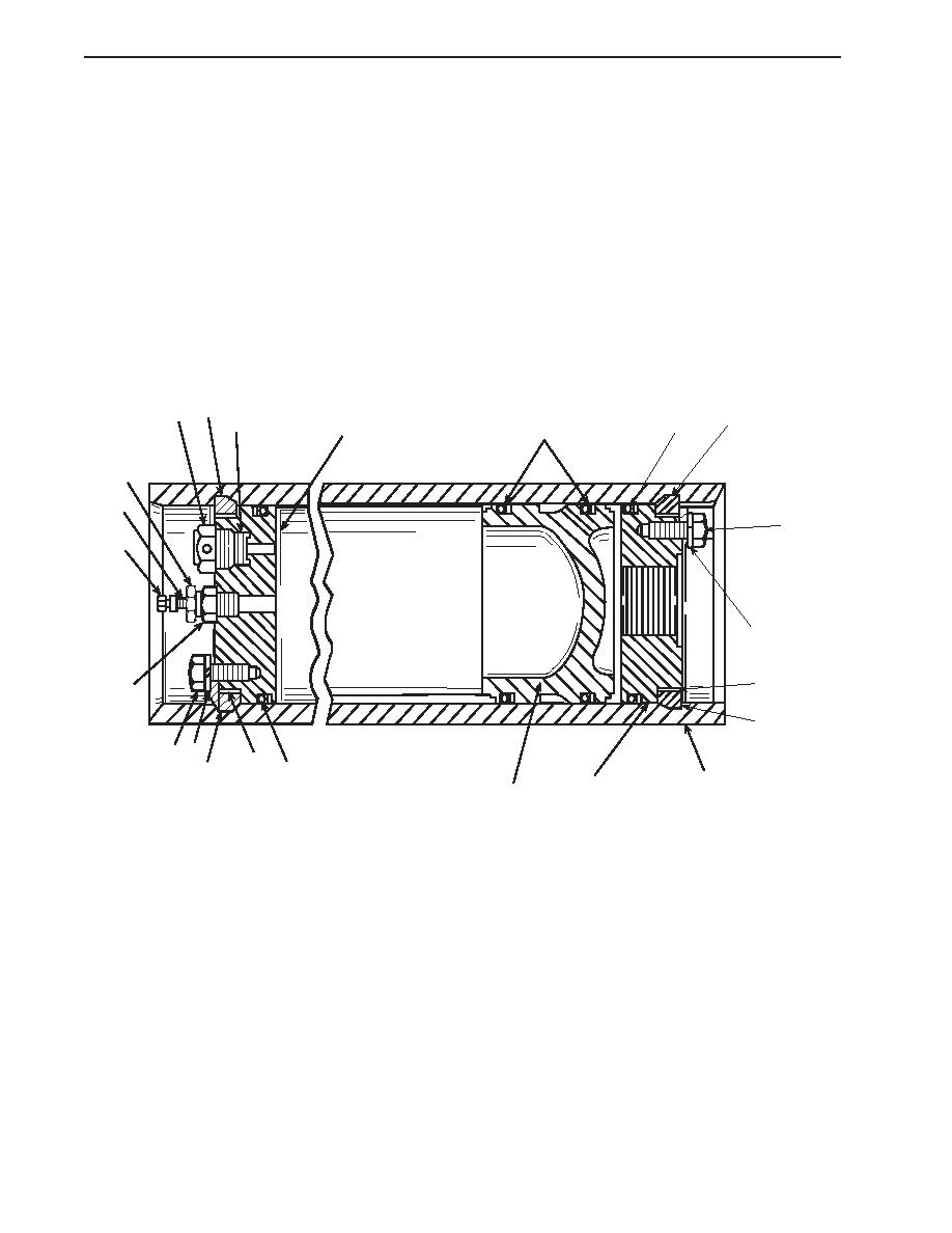
DISASSEMBLY (continued)
5.
Secure the housing (7) in a vise.
NOTE
Cotter pins, lockwashers, locking nuts, and similar locking devices shall be discarded after removal and replaced with
new cotter pins, lockwashers, locking nuts and similar locking devices.
6.
Remove the screws (8), lockwashers (9), and retaining plate (10) from the air end cap (11).
7.
Screw a 1/2 - 20 fitting into the air valve assembly (3) port.
8.
Push the air end cap (11) into the housing (7) far enough to permit removal of the ring segments (12 and 13). Remove the
ring segments and air end cap.
9.
Remove the O-ring (14).
10. Repeat steps 5-9 for the oil end cap (15).
12
5
12
6
14
11
17
3
2
8
1
9
10
4
13
9
8
10
13
14
7
15
16
11. Use a wooden dowel to push the piston (16) out of the housing (7).
12. Remove the seal rings (17) from the piston (16).
CLEANING
1.
If not already on, don protective gloves and goggles.
2.
Clean all metal parts with cleaning solvent and dry them with clean wiping rags.
INSPECTION
1.
Use a drop light to examine the bore of the housing (7). The bore must be free of scratches. Check the ring segment
grooves (12 and 13) for sharp, square edges to retain the ring segments. Remachine or replace the housing as required.
2.
Examine the air end cap (11) and oil end cap (15) for damage. Check the fitting threads and fusible plug (5) holder threads.
Repair or replace the air end cap and oil end cap as required.
0196 00-2
|
||
|
||


