
| Tweet |

Custom Search
|
|

|
||
 TM 55-1905-242-14
0197 00
DISASSEMBLY (continued)
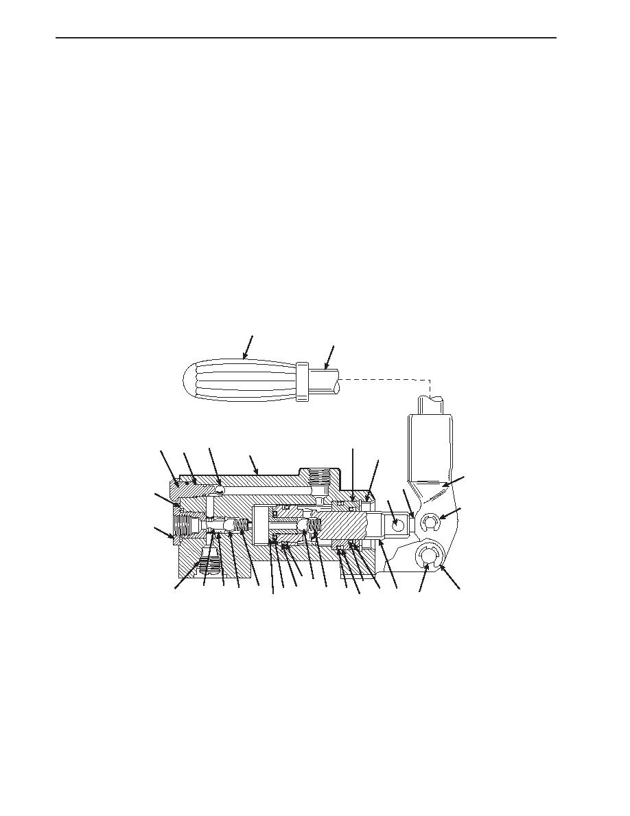
4.
Remove the retaining rings (4) from the clevis pin (5). Remove the clevis pin.
5.
Remove the retaining rings (6), clevis pins (7), and link (8) to remove the hand pump operating lever (3) from the
plunger (9).
6.
Remove the bleeder screw (10), O-ring (11), and ball (12).
7.
Remove the inlet oil fitting (13), O-ring (14), backup ring (15), O-rings (16 and 17), ball check valve (18), and spring (19)
from the pump body (20).
8.
Remove the retaining ring (21), bushing (22), and plunger (9) assembly from the pump body (20).
9.
Slide the bushing (22) off the plunger (9).
10. Remove the O-rings (23 and 24) and backup rings (25 and 26) from the bushing (22).
11. Remove the check valve seat (27), O-rings (28 and 29), backup ring (30), ball check valve (31), and spring (32).
12. Remove the pipe plug (33).
1
2
12
22
10
11
20
21
3
8
14, 15
6,7
6,7
13
29 31
24
16
19
30
33
17 18
32
4
28
26
9
23
5
25
27
CLEAN
1.
If not already on, don protective gloves and goggles.
2.
Clean all metal parts with cleaning solvent and dry them with clean wiping rags.
INSPECTION
1.
Inspect the springs for distortion, loss of tension, or broken coils. Replace the springs as required.
2.
Inspect the pins, balls, and plunger for burrs, nicks, or other wear. Remove minor nicks or burrs with crocus cloth.
Replace the pins, balls, and/or plunger as required.
0197 00-2
|
||
|
||


