
| Tweet |

Custom Search
|
|

|
||
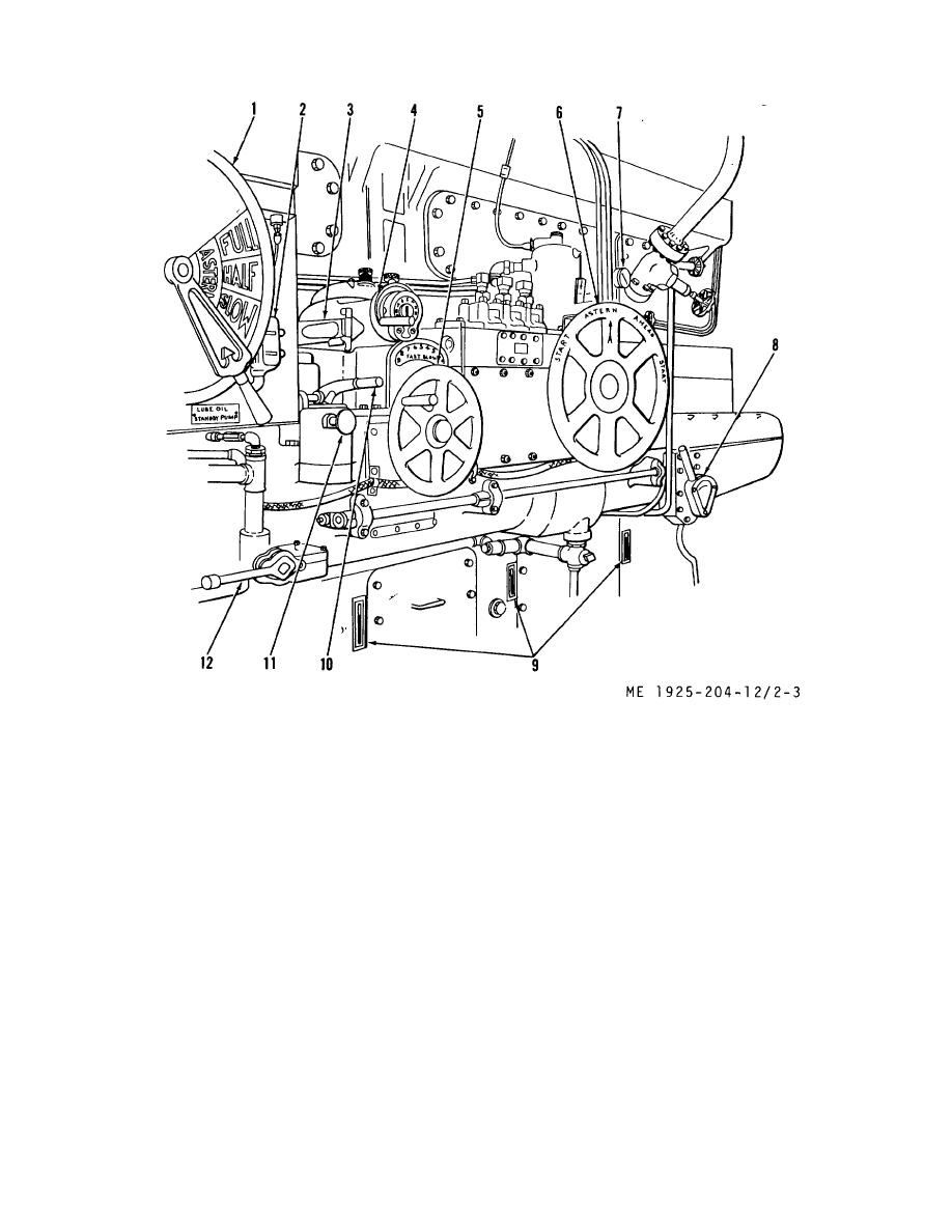 1.
Engine order telegraph
7. Airbrake pressure gage
2.
Steering gear switch
8. Cylinder relief lever
3.
Voice tube (to aft steering station)
9. Thermometers
4.
Governor hand control
10. Fuel shutoff reset lever
5.
Throttle handwheel
11. Emergency fuel shutoff
6.
Astern and ahead handwheel
12. Fuel filter selection lever
Figure 2-3. Main engine controls.
(2) Steering gear switch (2). This switch
communication between engine operator and the vessel
operator at the aft steering station.
operates motor that drives hydraulic pump of the
(4) Governor hand control (4). This control is
steering gear system. It is located on port side of
engine, near the engine order telegraph dial.
located on port side of engine, just above the throttle
Depressing RUN button starts motor and places steering
handwheel. It is used during maneuvering when quick
gear in operation. Depressing STOP button stops motor
change of engine speed is necessary.
and secures the steering system.
(5) Throttle handwheel (5). Located on port
(3) Voice tube (3). Located on port side or
side of engine just ahead of the astern/ahead
engine near governor hand control, this is a source of
2-5
|
||
|
||


