
| Tweet |

Custom Search
|
|

|
||
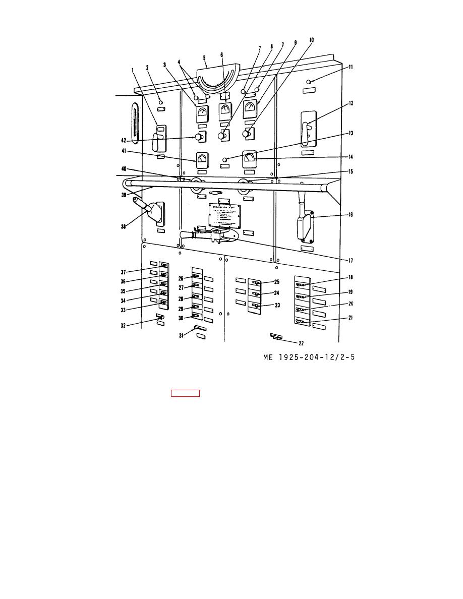 Figure 2-5. Main electrical control panel ( switchboard)
(1) Circuit breaker, generator No. 2 (1, Fig. 2-5). This
(5) Clinometer (5). Indicates the angle of roll of the tug
circuit breaker is used to open or close the electrical circuit
(in degrees).
between generator No. 2 and the control panel. In the event
(6) Steering motor amperage (6). Indicates the
circuit becomes overloaded the circuit breaker acts as a
amperage being used by the steering motor.
protective device and opens the circuit automatically.
(7) Shore power indicator light (7). When lighted,
(2) Power available light, generator No. 2 (2). This
these lights indicate that power is available to the control
signal light-, when lighted, indicates that power is available for
panel from the shore cable.
use from generator No. 2.
(8)
Generator voltmeter (9).
Indicates available
(3) Calibrating voltmeter (3). Indicates total voltage
voltage on the unit designated by selector switch (10).
available from generator selected on selector switch (10).
(9)
Voltmeter selector switch (10).
Selects the
(4) Ground lights (4). Indicates the location of
generator on which a voltage reading is to be taken.
grounded electrical circuitry by a change in brilliance.
(10) Power available light, generator No. 1
2-9
|
||
|
||


