
| Tweet |

Custom Search
|
|

|
||
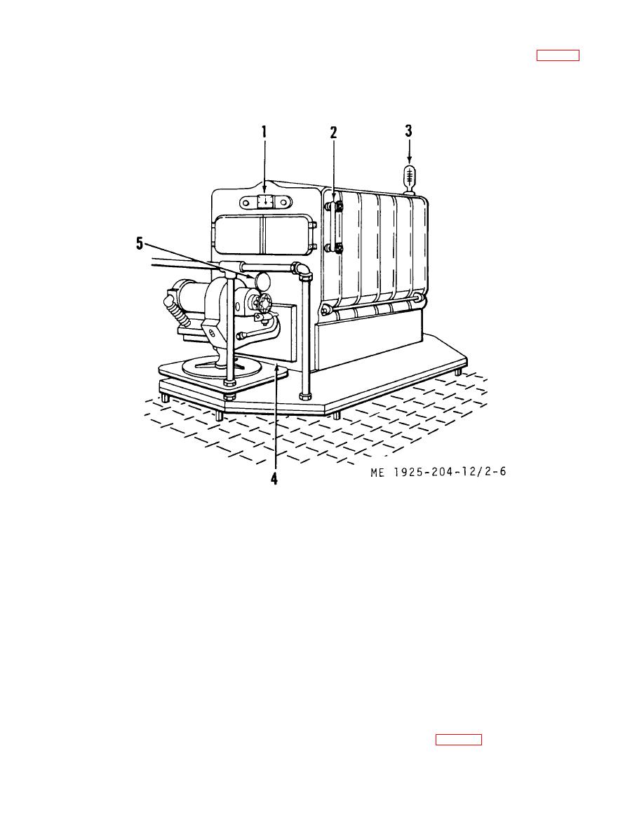 (4) Pressure and vacuum gage (1, fig. 2-6). The
during operation the stack temperature and helix will
cool, thereby closing the cold or starting contacts, and
pressure and vacuum gage is located on front of the
the burner will lock out after the preset time of 90
boiler. The normal pressure reading on this gage should
seconds.
be 5 psi, and should never exceed 10 psi.
1 Pressure and gage
4 Burner unit
2 skater gage
5 Sight glass
3. Pressuretrol
Figure 2-6 Heating boiler controls
(5) Water gage (2). The water gage is located on
(8) Air inlet shutter. The air inlet shutter is located
side of heating unit at top right front. The gage indicates
on side of the burner blower housing. Its purpose is to
actual level of water in the boiler. Unit should be
adjust the amount of air being admitted to unit burner.
secured immediately if water level disappears from the
(9) Oil burner cutout switch. The oil burner cutout
gage. The normal water level is at midpoint in the
switch is located adjacent to the oil burner. This switch
glass.
gives independent control of electric power to the burner
(6) Pressuretrol (3). The pressuretrol is located
unit.
at the top outboard end of the boiler. The function of
(10) Low water cutoff. The low water cutoff is
this control is to secure the boiler heating unit should
located on forward side of boiler. Its purpose is to
pressure exceed 10 psi.
secure the boiler heating unit if water level drops below
(7) Safety valve. The safety valve is located at
the safe operating level.
top of the boiler. Its function is to release the boiler
(11) Heating system control valves. The
pressure when pressure exceeds 10 psi.
location and identification of heating system control
valves are shown in table 2-1 below:
2-11
|
||
|
||


