
| Tweet |

Custom Search
|
|

|
||
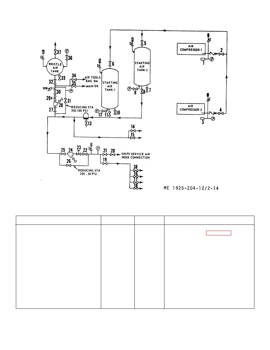 Figure 2-14. Compressed air system piping diagram.
Table 2-11. Compressed Air System Control Valve Positioning.
Operation
Open valve
Close valve
Procedure
To turn on air supply from com-
(2)
Start air compressors (para 2-15, C).
pressors to engine manifold.
(4)
(5)
(6)
(8)
(9)
(11)
(12)
(14)
(15)
To turn off air supply to engine.
(15)
To operate whistle tank and whistle.
(2)
(28)
If reducing station fails to supply air to whistle
(4)
(31)
section, open valve (31) slightly, so relief
(5)
(33)
valve does not pop off. Close valve (27).
(6)
(8)
2-36
|
||
|
||


