| Tweet |

Custom Search
|
|

|
||
 (2) To charge the general alarm batteries
proceed as follows-
(a) Move switch P10-1 (fig. 2-15) to ON
position.
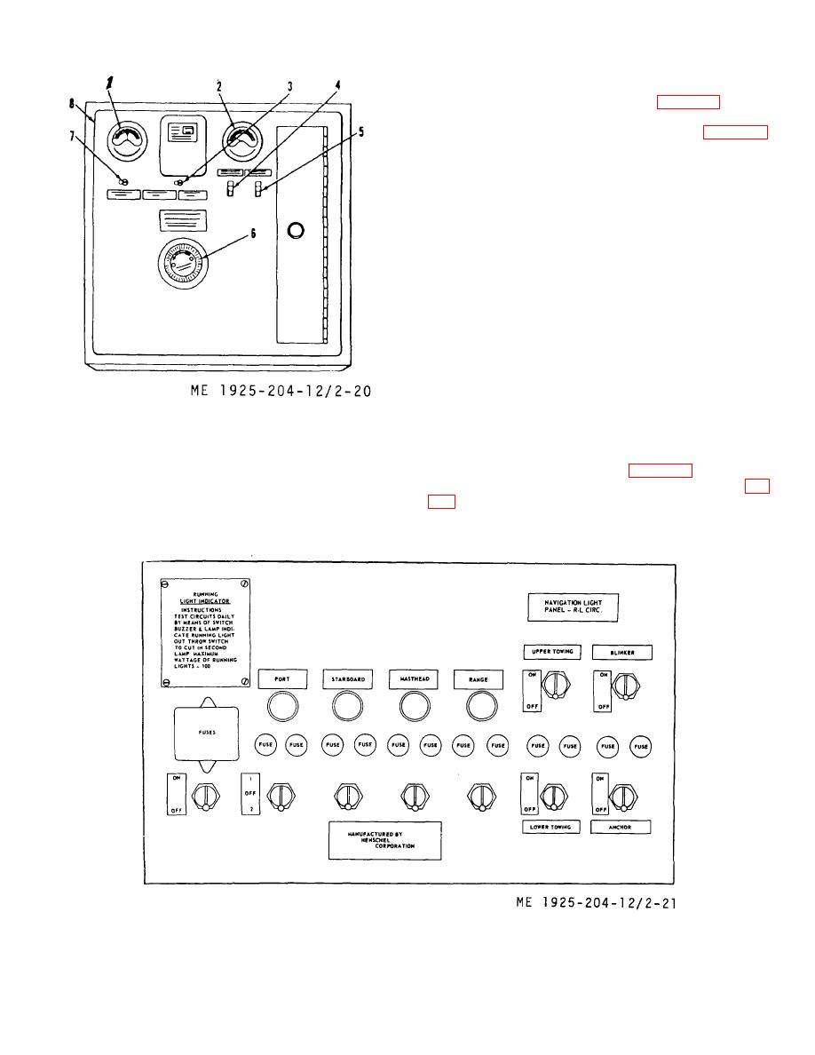
(b) Rotate rheostat control (6, fig. 2-20)
clockwise as far as it will go.
(c) Move main control switch (5) to ON
position.
(d) Move trickle charge switch (4) to OPEN
position.
(e) Move battery selector switch (3) to
BATTERY No. 1 on BUS.
(f) Move battery volt switch (7) to ON
position.
(g)
Turn
rheostat
control
(6)
counterclockwise until desired rate of charge (TM 9-
6140-200-15) is indicated on ammeter 12).
(h) To charge battery no. 2, move battery
selector switch (3) to BATTERY NO. 2 on BUS.
(i) To charge general alarm batteries by a
trickle, move trickle charge switch (4) to CLOSED
position.
(j) To secure the battery charging control
1.
5.
Main control switch
panel, reverse the procedures in steps (a) through (i)
2.
6.
Rheostat control
above.
3.
Battery selector switch
7.
Battery volt switch
e. Navigational Light Control Panel Operation.
4.
Trickle charge switch
8.
Panel access door
(1) This control panel (fig. 2-21) is supplied
from the main electrical control panel circuit RL (25, fig.
Figure 2-20. Battery charging control panel.
individual switching and fuses for the running lights,
towing lights, anchor light, and blinker light circuit.
Figure 2-21. Navigational light control panel.
2-42
|
||
 |
||