
| Tweet |

Custom Search
|
|

|
||
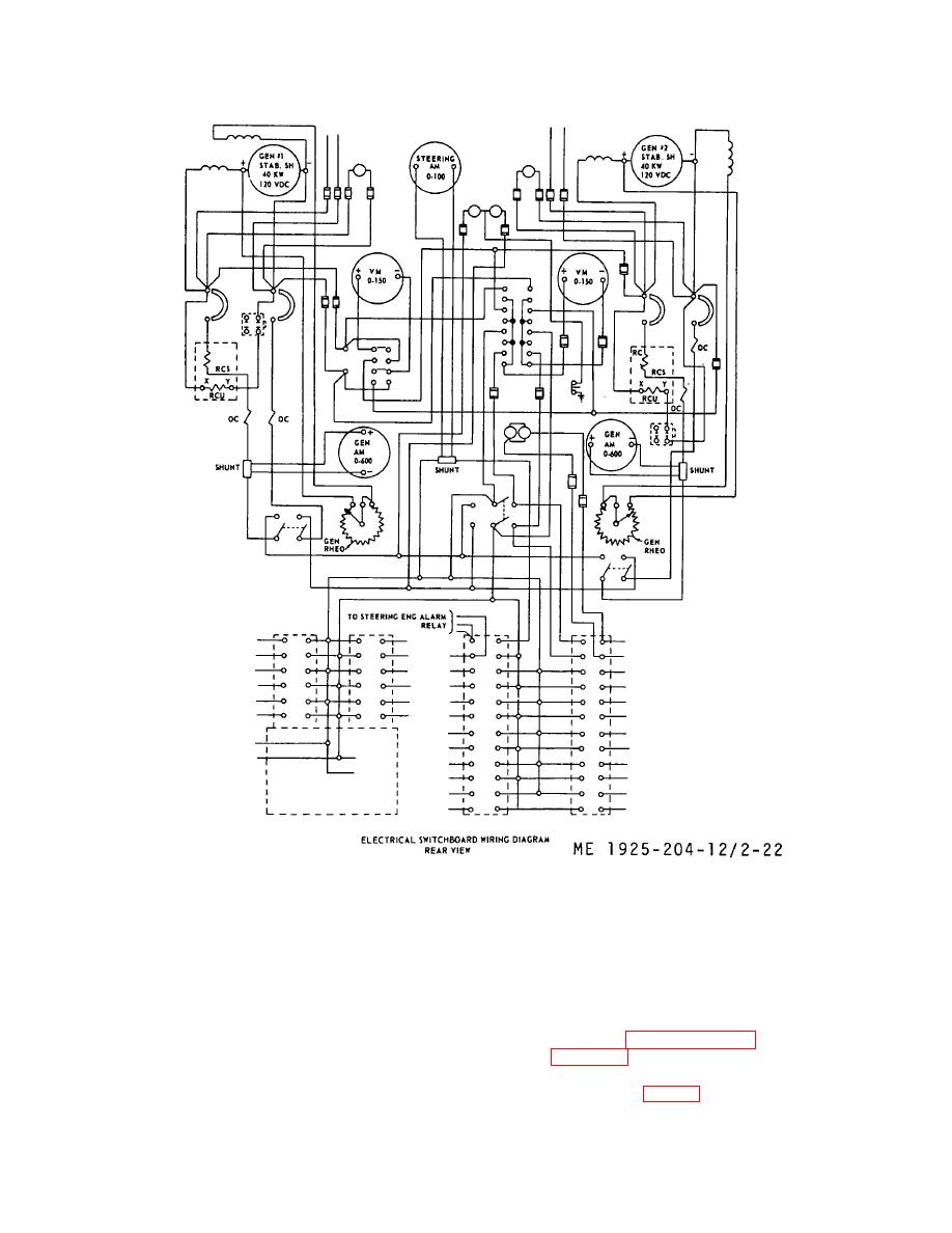 Figure 2-22. Main electrical control panel wiring diagram, rear view.
(1)
Provides the controls and instruments
(5)
Provides individual circuit overload
necessary for operation of the two generators.
protection for all auxiliary equipment by means of circuit
(2) Provides switching arrangements to go from
breakers.
ships generators to shore power, and from direct power
(6) Provides a ground detector to test the
to the various electrical loads throughout the tug.
generator and all power and lighting circuits for the
(3) Provides necessary switching to parallel the
presence of accidental grounds.
service generators.
(7) Operation of the various components listed
(4) Provides overload and reverse current
and described in paragraph 2-2j(1) through (41) above,
protection to service generators by means of the
and in figure 2-5, is described below:
generator circuit breakers.
(a)
Open or close circuit breaker for
generator no. 1 (12, fig. 2-5) or circuit breaker for
2-44
|
||
|
||


