
| Tweet |

Custom Search
|
|

|
||
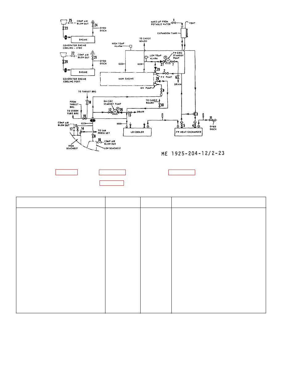 Figure 2-23. Engine cooling system diagram.
keyed to figure 2-23, lists the various operations to be
performed, the valve position for each and the
identifies each valve in the cooling system, gives its
procedure necessary to accomplish them.
location, function, and label description. Table 2-13, also
Table 2-13. Engine Cooling System Control Value Positioning.
Operation
Open valve
Close valve
Procedure
To cool port generator engine.
(20)
(22)
NOTE
(21)
Clean sea strainers daily, or more
often, if conditions demand continuous
cooling operation.
To cool stbd. generator engine.
(23)
(25)
NOTE
(24)
Clean sea strainers daily, or more
often, if conditions demand continuous
cooling operation.
To cool main engine normally.
(4)
(1)
These valves should remain in the
(5)
(7)
positions indicated whenever the
(11)
(6)
main engine is running.
(2)
(12)
(9)
(13)
(8)
(16)
(15)
(17)
(10)
(11)
(18)
(19)
To cool main engine, using standby
(7)
(1)
Start standby pumps.
pumps.
(27)
(2)
(29)
(6)
(4)
(16)
2-47
|
||
|
||


