
| Tweet |

Custom Search
|
|

|
||
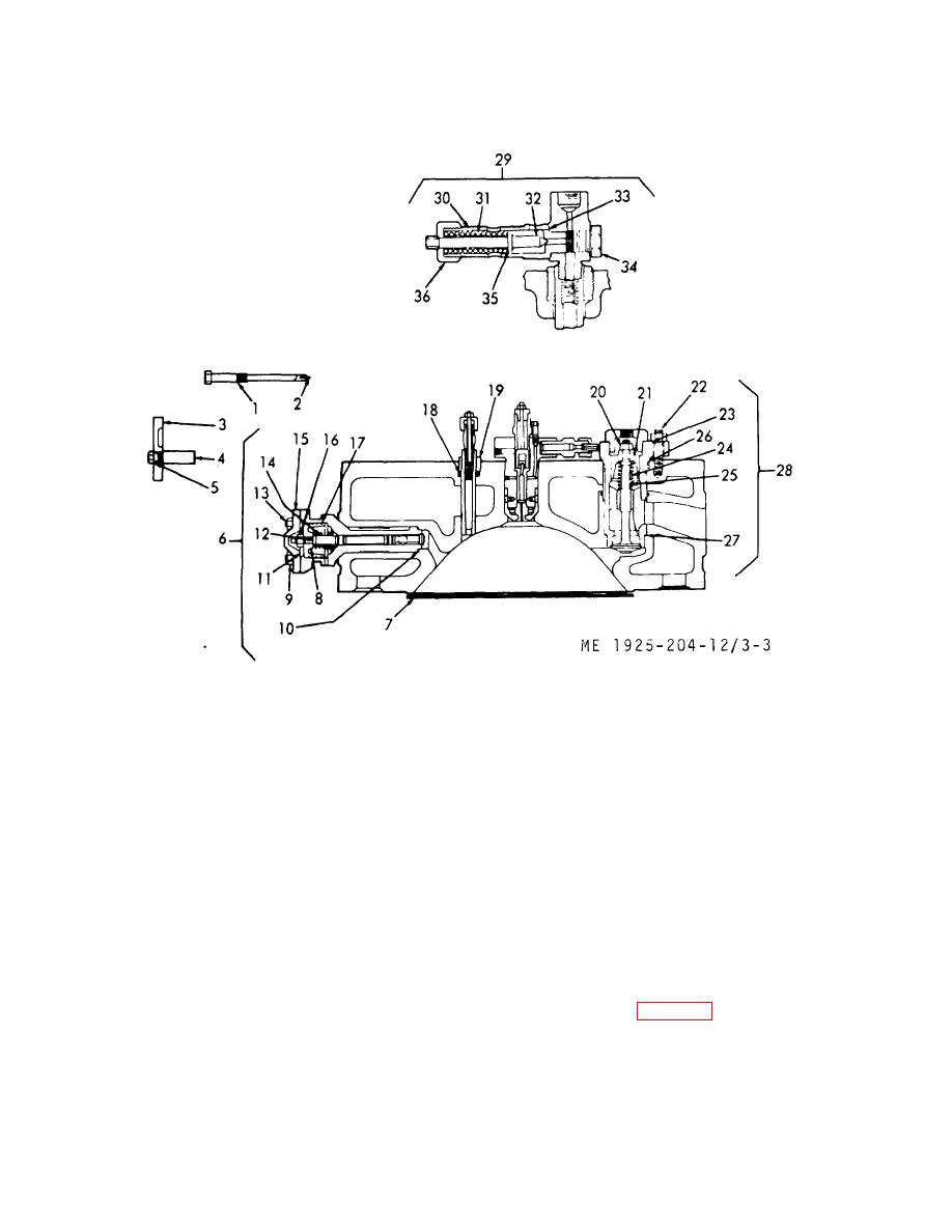 (1) Disassemble by backing off nut (36, fig.
(4) Clean all valve ports, and be sure that all
gasket surfaces are free of particles, ready for
33) and plug (34). Life valve (32), shim (35), and spring
(31) out of cage (30). Remove gasket (33).
installation.
d. Safety Relief Valve.
1.
Holder
13. Stud
25.
Valve
2.
Cartridge
14. Spring
26.
Gasket
3.
Gasket
15. Cover
27.
Gasket
4.
Post
16. Nut
28.
Valve
5.
Gasket
17. Ring
29.
Valve Relief
6.
Valve assembly
18. Packing
30.
Cage
7.
Gasket
19. Packing nut
31.
Spring
8.
Piston
20. Nut, w/cotter pin
32.
Valve
9.
Nut
21. Piston
33.
Gasket
10.
Gasket
22. Stud
34.
Plug
11.
Gasket
23. Gasket
35.
Shim
12.
Valve
24. Spring
36.
Nut
Figure 3-3. Cylinder head valves.
through (3) above. Place in a rack for safe keeping until the
(2) Inspect the spring (31). Replace a broken
cylinder head from which it was removed, is ready for
or weak spring.
installation.
(3) Clean valve (32) in clean fuel oil and wipe
e. Air Starting Check Valve.
dry with a clean cloth. Inspect face of valve for burn, or
(1) Disassemble by removing bushing cotter
bend. Replace a defective valve.
pin and nut (20, fig. 3-3) and lift out piston (21).
NOTE
Remove spring (24), then pull check valve (25) from the
The spring loaded safety relief valve may
cage.
have one or more shims.
When
(2) Clean the air starting check valve in fuel
assembling the valve be sure you can
oil. Wipe dry with a clean lint free cloth. Inspect
use the correct number of shims.
Assemble the spring loaded safety relief
(4)
valve in reverse order of disassembly given in steps (1)
3-23
|
||
|
||


