
| Tweet |

Custom Search
|
|

|
||
 deposit. Remove any ridge with fine
NOTE
emery cloth to prevent ring damage
Use new gaskets at all positions on
when piston is lifted from cylinder
assembly, and remove tags from
bore.
nuts as they are installed on same
studs from which removed.
(1)
Install head stud nuts hand tight, then torque
to 100 ft. lbs. Inspect nuts for an even drawdown. If
drawdown has been satisfactory, retorque (in same sequence)
to 800-940 ft. lbs.
(2)
Retighten stud nuts at end of 100 hours of
operation.
NOTE
See paragraph 3-12 for fuel injector
repair, removal, and installation
instructions.
3-7. Piston, Connecting Rod, Bearings, Rings, and
Cylinder Sleeve
a. General. The piston is of the trunk type, oil
cooled, and fitted with five piston rings. The connecting
rod is of forged steel and is fitted to the piston by a pin
and sleeve bearing. It is fitted to the crankshaft by a
box type bearing assembly. The bearings are babbitt
type inserts. The cap and box (bearing shells) are not
interchangeable.
When one requires replacement,
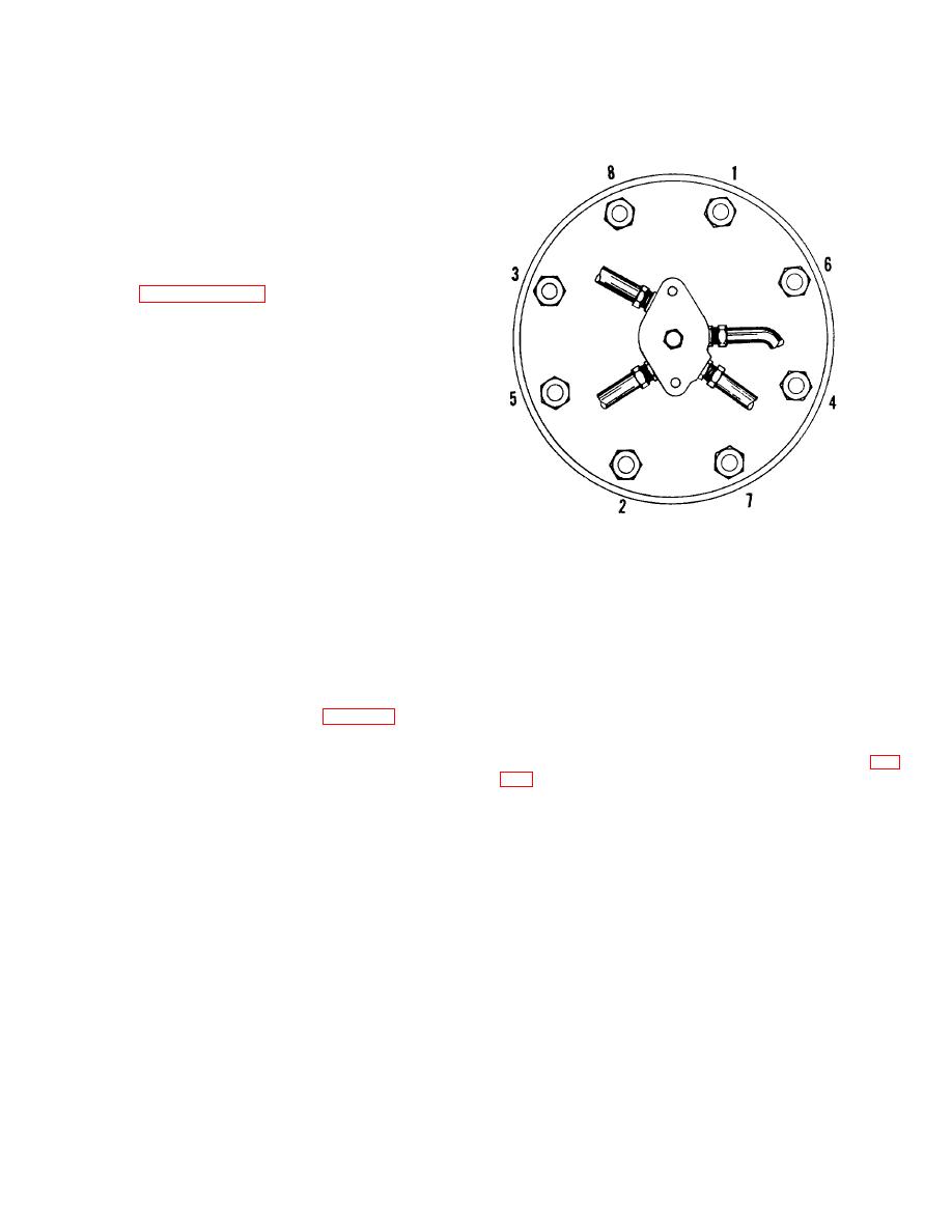
Figure 3-5. Sequence of applying torque to
replace both.
holddone nuts..
b. Piston, Connecting Rod, and Rings.
(3)
Use the flywheel ratcheting device to turn
NOTE
engine over until the desired piston is at top dead center.
When a cylinder head is being
(4)
Disconnect the cylinder oil baffle by
removed for access to the piston
unscrewing the capscrew securing the cooling oil stationary
group, do not remove fuel injector or
pipe flange to the outlet pocket, and the nuts at the opposite
valves from the cylinder head.
side of the baffle. The foot of the rod will now go through the
Disconnect and cover line ends and
baffle opening. Remove the baffle by spreading it at the split
section until it will clear the rod.
ports only, to prevent contamination.
(5)
Install the two 3/4 in. eyebolts in tapped holes
(1)
Remove the cylinder head (para. 3-6).
provided in piston. Connect sling to eyebolts and a hoisting
(2)
Remove the crankcase inspection plates from
device, then take up slack.
both sides of the upper base, for the appropriate cylinder.
(6)
Remove two cotterpins and two nuts (9, fig.
NOTE
After the cylinder head is removed,
inspect the counterbore at top of
cylinder for a ridge of carbon
3-25
|
||
|
||


