
| Tweet |

Custom Search
|
|

|
||
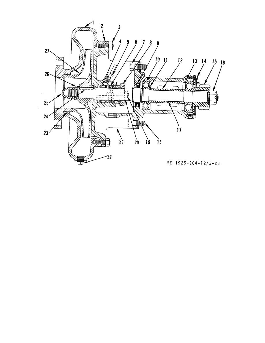 1.
Volute
10.
Bearing
19.
Nut
2.
Gasket
11.
Washer
20.
Clamp
3.
Nut
12.
Spacer
21.
Volute bracket
4.
Ring
13.
Bearing
22.
Plug
5.
Connector
14.
Capscrew
23.
Wearing ring
6.
Packing
15.
Driven gear
24.
Key
7.
Nut
16.
Nut
25.
Locknut
8.
Packing gland
17.
Shaft
26.
Lockwasher
9.
Oil seal
18.
Gasket
27.
Impeller
Figure 3-23. Fresh or raw water pump, cross section.
(5) Remove the safety wire from capscrews (14),
c. Disassembly.
remove the capscrews, then remove retainer and bearing (13)
(1) Remove nuts (3) and remove volute (1), then
off shaft (17).
remove wearing ring (23).
(6) Slide spacer (12) and washer (11) off shaft (17).
(2) Remove locknut (25), lockwasher (26), and the
(7) Remove shaft (17) from support bracket, then
impeller (27) off shaft (17).
remove bearing (10), oil seal (9), and ring (4).
(8) Remove the connector (5) from the packing housing
NOTE
in support bracket (21).
The impeller is keyed to the shaft,
d. Cleaning, Inspection, and Repair.
therefore a wheel puller may be required to
(1) Wash all pump parts in clean fuel oil and wipe dry
remove it
with a lint free cloth. Do not blow bearings dry.
(2) Inspect bearings for roughness, signs of wear, or
(3) Remove nuts (19), clamp (20), and packing gland
overheating (discolored). Replace a
(8).
(4) Remove the packing (6). Remove cotterpin from
nut (16), then remove the nut. Pull the driven gear (15) from
shaft (17).
3-56
|
||
|
||


