
| Tweet |

Custom Search
|
|

|
||
 TM 55-1925-204-12
(b) Remove the cover mounting screws;
(c) Disconnect the lubricator drive link (4,
lift cover off the housing, then carefully remove the
gasket. Save for reuse at installation.
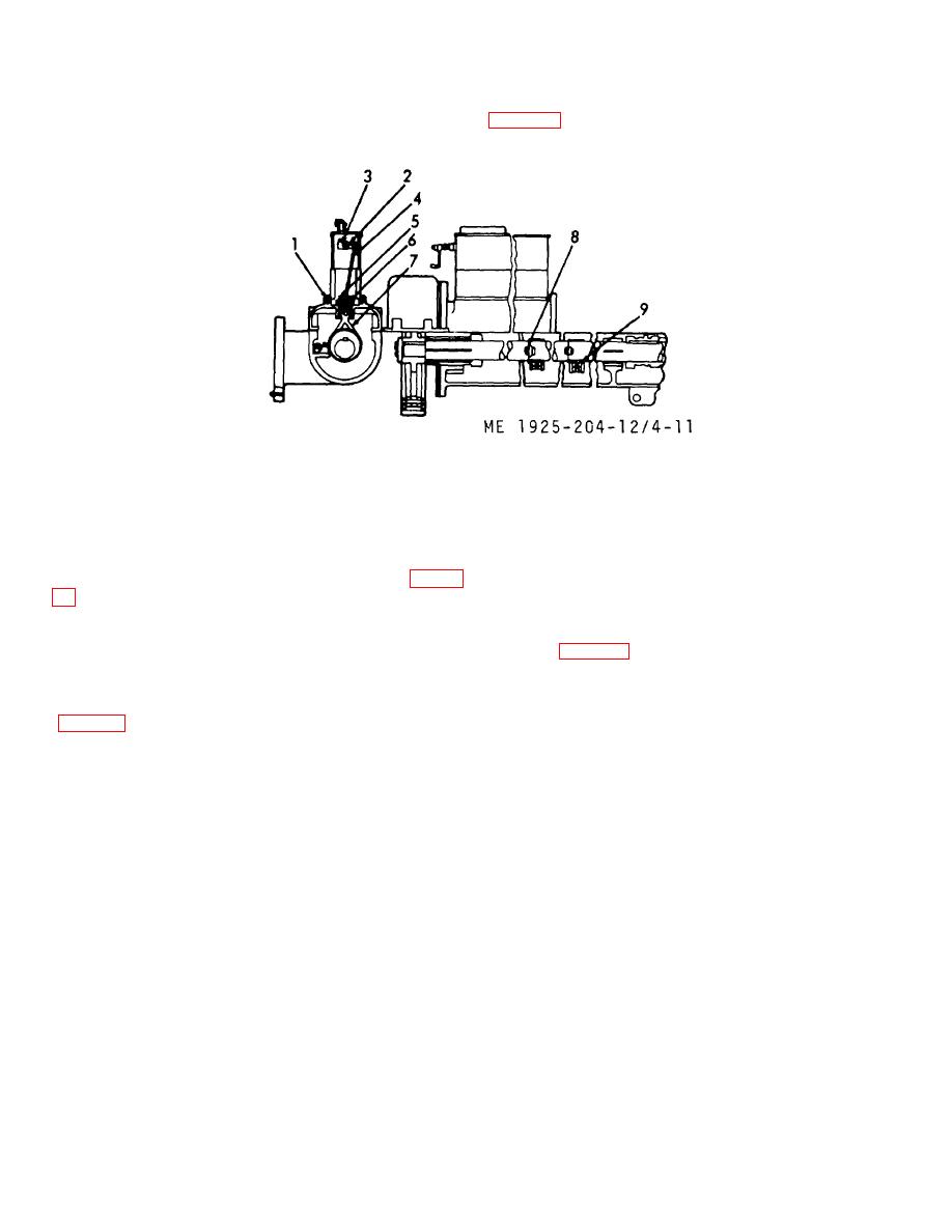
1.
Gasket
6.
Crosshead
2.
Arm
7.
Strap
3.
Pin
8.
Bolt
4.
Link, lubricator drive
9.
Key
5.
Sleeve
Figure 4-11. Lubricator drive.
(b) Use clean fuel oil and wash the
interior of the lubricator, then blow dry with ships service
air. Do not turn hand crank while washing the reservoir.
camshaft housing, and move it to a workbench.
(c) Drive the split end taper pin out of the
(2) Disassembly. Under normal conditions,
collar (8, fig. 4-12). Then loosen the shaft bearings at
disassembly for repair is infrequent, but when the
each end of reservoir by backing off the locknut at each
pumping unit (s) cannot be adjusted to the correct
bearing.
discharge rate, proceed as follows:
(a) Move container under the drain cock
the reservoir.
4-21
|
||
|
||


