
| Tweet |

Custom Search
|
|

|
||
 TM 55-1925-204-12
(3) Test and Repair.
Test continuity and
electrical contacts. Replace a defective tachometer.
Repair by replacing a defective sending unit.
(4) Installation. Install by reversing the
procedures in step (1) above.
e. Pyrometer.
(1) Test. Use available test equipment to
verify scale accuracy of the six thermocouple readouts.
Replace a defective pyrometer.
(2) Removal.
(a) Tag and disconnect the thermocouple
leads from rear of pyrometer (5).
(b) Remove the eight screws from frame
that secures pyrometer to panel (7).
(3) Installation.
Install the pyrometer by
reversing the procedures in step (2) above.
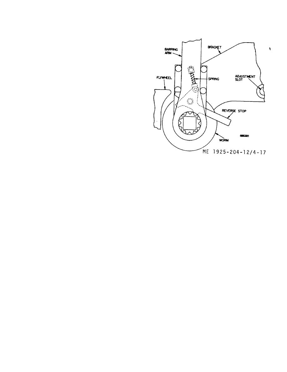
4-19. Flywheel Assembly
a. General. The flywheel is keyed to the drive end
of the crankshaft, and coupled to the Kingsbury thrust
bearing stub shaft. The flywheel jacking device (flywheel
turning) is mounted on deck at port side of engine. The
flywheel brake shoe is installed on port side, with the air
cylinder above the flywheel guard pulling the application
Figure 4-17. Flywheel jacking device.
lever. The brake air pressure gage indicates available air
pressure, and is mounted in line at rear of engine control
station. The cam operated pilot air valve controlling the
(1) Disassembly.
air brake operation is installed on camshaft housing
(a) Remove barring arm from worm.
behind the astern/ahead handwheel, and is activated by a
(b) Loosen pin and remove spring.
cam on handwheel at the stop position. There is a globe
(c) Remove ratchet pawl, then remove
shutoff valve in air line for pressure regulating valve to
worm from bracket. Remove the two ball bearings from
reduce the starting air pressure of 250 psi, to the 125 psi
the worm.
required for the brake application. Relay control is
(2) Cleaning, inspection, and repair.
maintained by a pressure regulator.
(a) Clean all parts removed in clean fuel
b. Flywheel Jacking (Ratcheting) Device. Use the
oil and wipe dry.
ratcheting device to turn engine over when performing
(b) Inspect spring for weakness, bend, or
maintenance, by moving barring arm, after setting ratchet
break. Replace a defective spring. Inspect pin for
pawl for direction it is desired to turn.
Perform
straightness. Replace a defective pin.
maintenance as follows.
(c) Inspect bearings for wear, and
smoothness of operation. If worn, or rough, replace.
4 -30
|
||
|
||


