
| Tweet |

Custom Search
|
|

|
||
 TM 55-1925-204-12
(a) Support the cylinder head, bottom
(2) Rocker arms, push rods, and valves. Install
side up, on 2 in. thick wood blocks.
the valves, push rods and rocker arms by reversing the
(b) Use the valve guide remover (table
procedures in c.(2) above.
f. Installation. Make a pre-installation inspection of the
d. Cleaning, Inspection, and Repair.
cylinder head just prior to installation, by checking studs for
(1) Cylinder head. After the cylinder head has
damaged threads; extruded areas around stud holes; liner
been stripped of its components parts, proceed as follows:
height in relation to the cylinder block; that tops of pistons are
(a) Clean the cylinder head thoroughly,
clean and free of foreign material; no burrs in any bore or
then brush all gasket surfaces to be sure no bits or pieces
counterbore, then check to assure that all push rods are
cling to the cylinder head.
threaded fully into the clevis until end of rod protrudes from
(b) Remove all carbon and dirt from the
top of clevis.
exhaust passages (ports).
(1) Cylinder head installation.
(c) Pay particular attention to gummy
(a) Position compression gaskets, water,
sludge in push rod bores, or domes of cylinders on bottom of
and oil seals on block, as follows:
the cylinder head.
1. Position a new
gasket on
(d) Inspect the cam follower bores in the
cylinder liners.
cylinder head for scoring or wear. Light score marks may be
2. Position new seal rings in the
cleaned up with crocus cloth dampened in fuel oil. Check that
counterbores of the water and oil holes in cylinder block.
maximum diameter of bore in a used head does not exceed
3. Install a new oil seal in the
1.065 inch. Replace a head where bores are excessively
groove at the perimeter of the cylinder block.
worn.
CAUTION
Never reuse old gaskets and seals.
NOTE
Incorrect placement of new gaskets could
Thoroughly clean a replacement cylinder
block lubricating passages and damage
head of all rust preventive compound by
the engine.
soaking the head in clean fuel oil, then go
over the head and through all of the
(b) Wipe the under side of the cylinder
passages with a soft bristle brush. Blow
head clean. Insert hoist hooks in the vent holes of the
all oil passages dry with compressed air.
cylinder head, or the eyes of lifter brackets (if installed).
(c) Make a final visual check of all gaskets
(2)
Components of cylinder head.
and seals.
(a) Clean all parts removed from the
(d) Lower cylinder head over studs, until
cylinder head in clean fuel oil, except the fuel injectors. The
the head is about 1/2 inch above the block.
procedure to be used on fuel injectors is described in
(e) Recheck position of all gaskets and
seals.
(b) Inspect springs for tension, breaks, or
(f) Lower head into place. After the head
bends. Replace a defective valve or push rod spring.
is in place, loosen the lifter bracket-to-cylinder attaching
(c) Scrape all carbon from stern and valve.
capscrews before installing nuts on studs. If this is not done,
Stems should be smooth. and free from scuff marks. Valve
the cylinder head may be prevented from seating properly
faces should be smooth, unpitted, and free of carbon ridges.
against its gaskets and the cylinder block.
If any of the above conditions exist, replace the defective
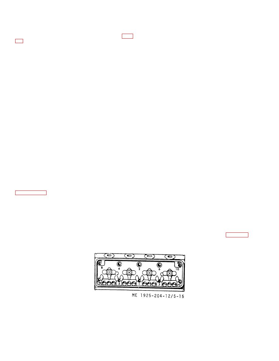
(g) Draw the head down gradually and
valve.
uniformly to insure a good seal. Tighten nuts to a torque of
e. Reassembly.
180-190 ft. lbs. in the sequence shown on figure 5-15.
(1) Fuel injectors. Install the fuel injectors by
reversing the procedure in c.(1) above.
Figure 5-15. Sequence of tightening cylinder head nuts.
5-18
|
||
|
||


