
| Tweet |

Custom Search
|
|

|
||
 TM 55-1925-204-12
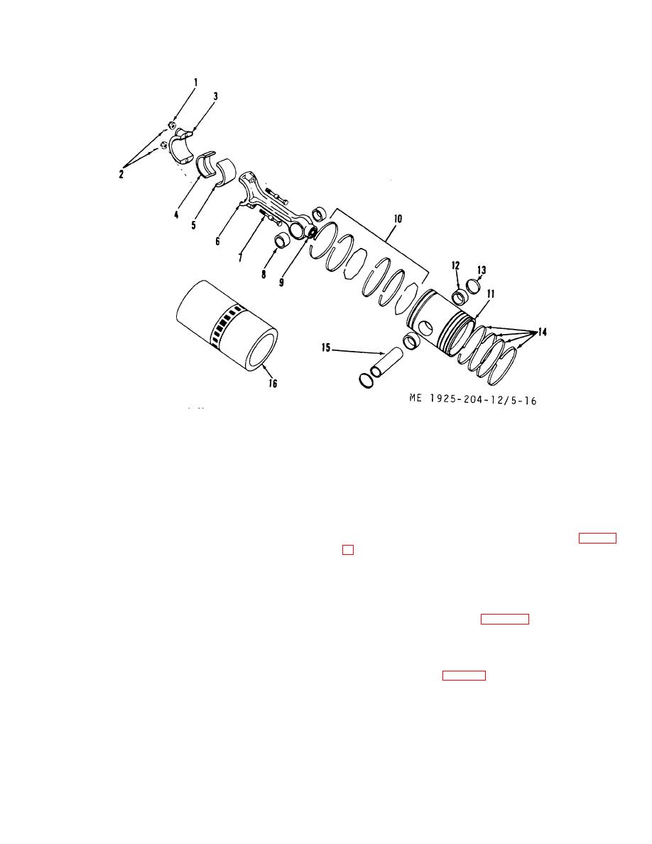
1.
Nut
9. Spray nozzle
2.
Cotterpin
10. Oil rings and expanders
3.
Bearing cap
11. Piston
4.
Lower bearing half
12. Sleeve bearing
5.
Upper bearing half
13. Cap
6.
Connecting rod
14. Compression rings
7.
Bolt
15. Pin, piston
8.
Sleeve bearing
16. Cylinder liner
Figure 5-16. Piston, connecting rod,cylinder and rings
(2) Remove piston pin (15) and separate rod (6)
(4) If cylinder liners have been removed (para 5-
from piston (11).
(3) Drive remaining cap (13) from piston.
top of cylinder is clean so that cylinder liner will fit properly.
(4) Remove rings (10 and 14) from the piston.
(5) If damaged, remove sleeve bearings (8) from
NOTE
connecting rod (6), and sleeve bearings (12) from the piston
Liners may be cleaned without removal if
(11).
inspection shows their condition does not
d. Cleaning, Inspection, and Repair.
warrant removal (see para 5-51.
(1) Remove all carbon from ring grooves of
piston. Grind the end of a discarded ring section and use for
(5) Measurement of pistons and bore sizes in
scraping carbon from grooves.
cylinder should be taken at room temperature (70 ).
F
(2) Clean oil holes in piston bottom with a 3/32-
Position a thickness gage leaf of 0.005 inch between cylinder
inch drill bit in a hand drill.
liner and piston skirt (fig. 5-17). Fit is correct if piston (less
(3) Clean piston thoroughly (inside and out) with
ring and pin) slides through the liner of its own weight. If a
fuel oil, and dry with dry compressed air. If gummy deposits
bind exists, remove piston and examine both piston and liner
resist fuel oil, use solvent Fed Spec P-D-680 and dry with
for burrs. Remove burrs with a flat honing stone.
compressed sir.
5-20
|
||
|
||


