
| Tweet |

Custom Search
|
|

|
||
 taper. Discard liners that are cracked or excessively scored.
NOTE
(4) When a liner has been in use for an extended
Honing of liners should be accomplished
period, the inside surface of the liner becomes very smooth.
while liner is in a fixture ( a scrap cylinder
This is known as a "glazed bore". When seating new rings,
block makes an excellent fixture).
this glaze must be removed, even though liner is within
However, if liner must be honed in the
dimensional specifications. Before installing the liner in the
block that must be used when assembling
cylinder block, work a honing tool with a 120-grit stone up and
the engine, the engine
must
be
down in liner bore several times, to remove the glaze. This
dismantled and thoroughly cleaned to
honing will also remove any ridges formed at top of piston
remove all abrasive material.
travel.
e. Installation.
(1) Wipe inside and outside of liner clean, and be
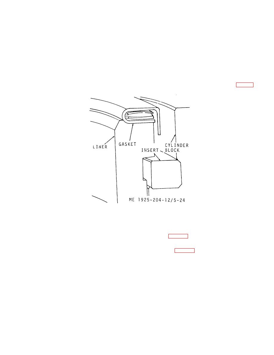
sure bore in block is also clean. Also, be sure the counterbore
in block is clean so the liner insert will fit properly (fig. 5-24).
Figure 5-24. Cylinder liner mounted in block.
(2) Assure that liner insert is in place on the
between bolt heads and the flywheel, to prevent bolt heads
counterbore.
from scoring the flywheel. The power generator ( elco Model
D
(3) Push the liner into the block until liner flange
1-3644) is directly, connected to the engine flywheel.
rests on the insert. If the liner does not slide easily into
Doweled into position, a flange on generator shaft is bolted to
position, withdraw the liner, rotate it 90 and reinstall it. Do
the flywheel (para 5-29).
not use excessive force in installing the liner.
b. Removal.
(4) Clamp the liner in place with a holddown
(1) Disconnect
power
generator from the
clamp, and measure distance from top of liner to top of block
engine flywheel (para 5-29).
with a dial indicator. The liner flange must be 0.045 to 0.050
inch below the surface of the block. However, even though all
NOTE
of the liners are within these specifications, there must not be
If the flywheel drive flange, for bolting
over 0.002 inch difference in depth between any two adjacent
generator matching flange has an internal
liners. If the above limits are not met, install the liner in
spline, remove the drive flange before
another cylinder and recheck, or use a new liner.
attaching flywheel lifting tool.
5-6. Flywheel Assembly and Housing
(2) Attach flywheel lifting tool with two 7/16-14
a. General. The flywheel is bolted securely to the end
bolts of suitable length after removing the six flywheel
of the crankshaft with six bolts and is doweled in two places.
attaching bolts.
Since one of the bolt holes is offset, the flywheel can be
(3) Attach a chain hoist, or other lifting device to
attached to the crankshaft in only one-position. Self locking
support the flywheel.
bolts are used to secure the flywheel. A scuff plate is used
5-27
|
||
|
||


