
| Tweet |

Custom Search
|
|

|
||
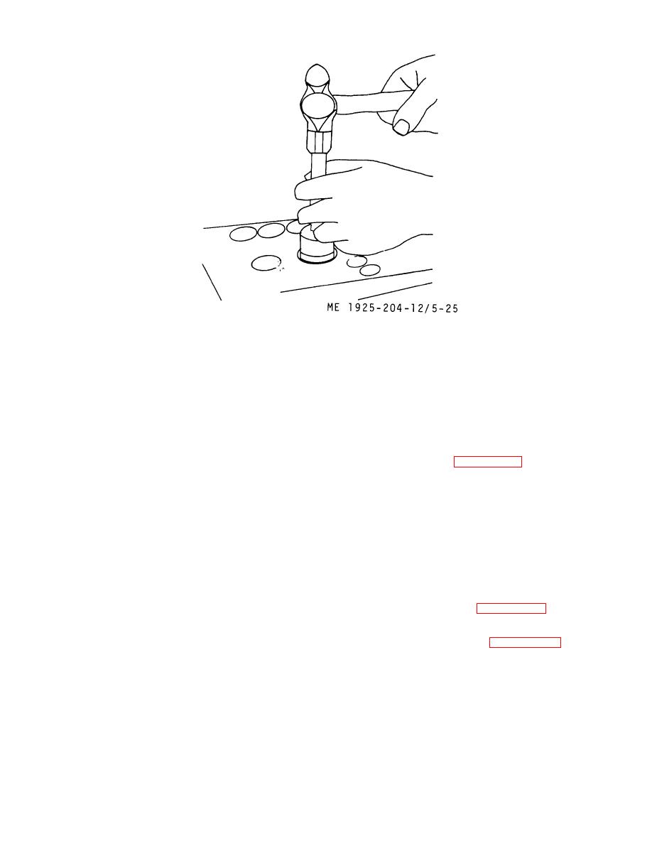 Figure 5-25. Installing valve seat.
6. Replace remaining valve seats
(d) When valve and seat have a uniform
as necessary, in a similar manner.
gray appearance, apply a small amount of Prussian blue or
white chalk on valve face. Wipe off excess so just a faint
(3) Reconditioning, or seating new valves.
trace of blue remains. Insert valve 'and turn valve on seat one
(a) Position cylinder head on workbench,
complete revolution under slight pressure. If a light ring
bottom side up.
appears completely around the seat, valve is properly seated.
(b) To grind valves, put a small quantity of
If the ring is not complete, valve and seat are not making
grinding compound on valve faces. Grind valves with a light,
complete contact and must be reground until proper
but firm, pressure letting the light valve grinding spring lift the
measurements are obtained.
valve grinding tool handle. As soon as the "grinding feel"
diminishes, wash valve and valve seat in fuel oil, and examine
(4) Installation. Install the valves, springs, caps,
seat and valve. If valve seat or face has lines, either the valve
and locks as described in paragraph 5-3.
grinding compound was ground out, or too much pressure
c. Camshaft and Gear Train. The camshaft is located
was applied, or valve was not lifted off seats often enough
near top of the cylinder block, on the blower side. The
during grinding operation.
In either case the grinding
balance shaft is opposite, and, the gear train is located at
operation must be repeated. Excess grinding can sometimes
flywheel end of the engine. The cam and balance gears are
be prevented by removing the glaze on the valve seat prior to
driven by the idler gear, which receives its power from the
grinding. This is done by placing a circular piece of fine
crankshaft timing gear.
emery paper, slightly larger than the valve post, over stem of
(1) Removal. While the camshaft itself can be
old valve. When valve is placed in position, emery paper
removed without removing the flywheel housing, the following
comes in contact with valve seat. With a firm steady pressure
procedure is given in order that the idler gear and bearing will
on valve grinding tool, rotate valve several revolutions.
be uncovered for sequential maintenance, along with the
(c) In grinding valves and seats, finished
bearings and thrust washers of both cam and balance shaft.
seat should have contact surface width of no more than 1/8
inch to give good seating. Finished contact surfaces greater
(a) Refer to paragraph 5-2 and remove all
than 1/8 inch should be reported to Direct Support
accessories necessary to the removal of the front balance
Maintenance level.
weight cover and the flywheel housing, including disconnect of
the power generator described in paragraph 5-29.
5-30
|
||
|
||


