
| Tweet |

Custom Search
|
|

|
||
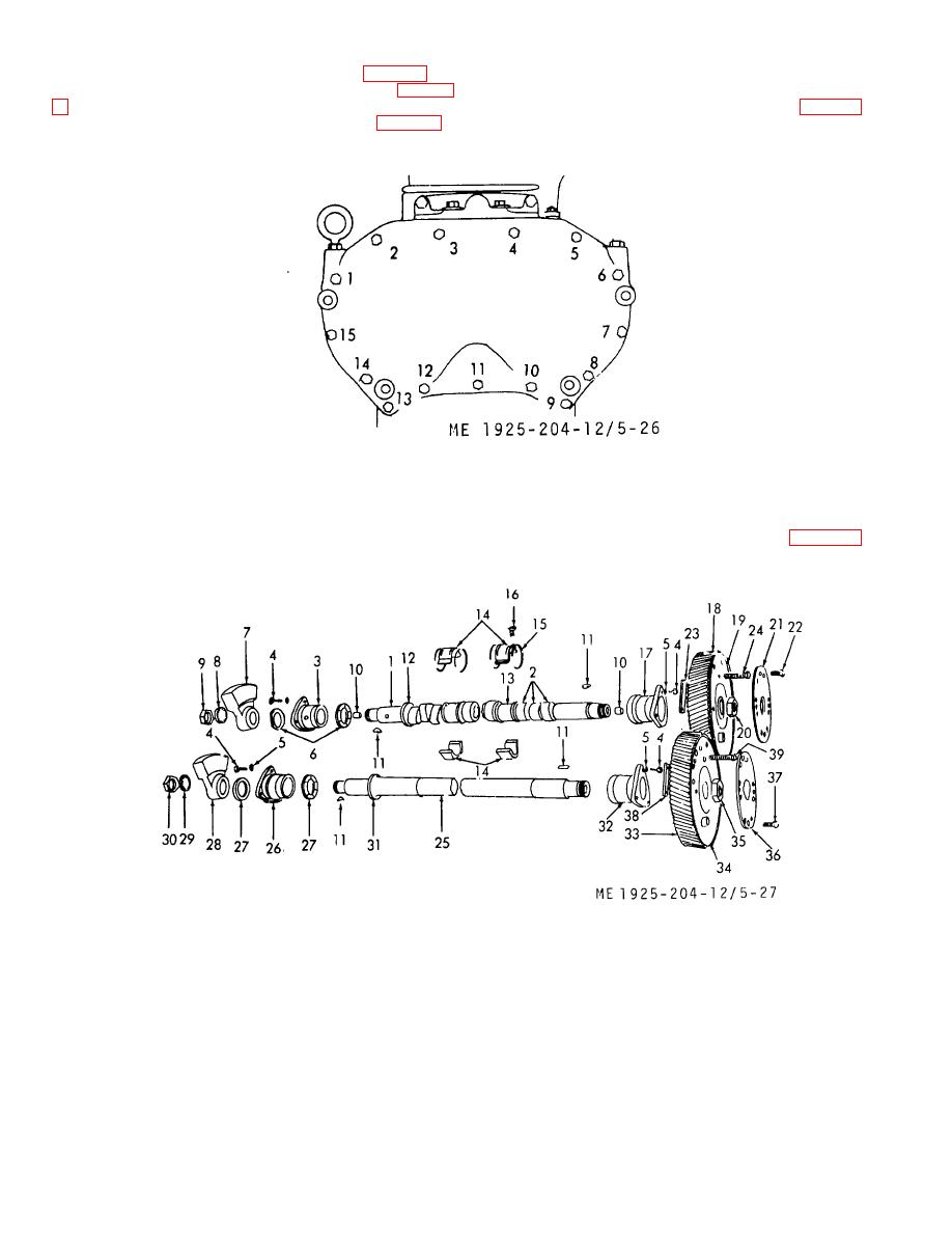 (b) Remove the cylinder head (para 5-3).
(e) Remove the fifteen capscrews, lock-
washers, and plain washers securing the balance weight
(c) Remove the flywheel housing (para 5-
cover to the cylinder block and front end plate (fig. 5-26).
(d) Remove the heat exchanger (para 5-2).
Figure 5-26. Balance weight cover removal and capscrew tightening sequence.
(f)
Remove the two capscrews attaching the
(h)
Shape a block of wood to fit between the
lifter bracket to the cylinder head (if step (b) above has been
two balance weights, or wedge a clean rag between the cam
delayed) then attach lifting device to lifter bracket.
and balance shaft gears on rear of the engine.
(g)
Loosen and remove balance weight cover
(i)
Remove capscrews (22, fig. 5-27) then
from the gasketed surface. Remove the gasket.
remove the nut retainer (21).
1.
Camshaft
9. 1Nut
17. Bearing, rear
24.
Capscrew
32.
Bearing. rear
2.
Cam
10. Plug
18. Gear
25.
Balance shaft
33.
Gear
3.
Bearing, front
11. Key, machine
19. Weight
26.
Bearing
34.
Weight, integral
4.
Capscrew
12. Thrust shoulder
20. Nut
27.
Thrust washer
35.
Nut
5.
Lockwasher
13. Journal
21. Retainer, nut
28.
Balance weight
36.
Retainer. nut
6.
Thrust washer
14. Bearing, intermediate
22. Capscrew
29.
Lockwasher
37.
Capscrew
7.
Balance weight
16, Lockring
23, Balance weight
30.
Nut
38.
Balance weight
8.
Lockwasher
16. Setscrew
31.
Thrust shoulder
39.
Capscrew
Figure 5-27. Typical camshaft and balance shaft details.
5-31
|
||
|
||


