
| Tweet |

Custom Search
|
|

|
||
 (3) Remove covers and gaskets from body.
(4) Remove capscrews and lockwashers from
cover then remove cover, pin, and sleeve bearings.
(5) Remove gears.
idler gear support, then
remove shaft. Remove keys from shaft.
(6) Wash the screen in clean fuel oil and blow dry
with compressed air.
(7) Use the new parts in the lubricating oil pump
service parts kit, to replace similar parts. Discard the old
parts.
(8) Reassemble by reversing the disassemble
procedure.
d. Installation.
(1) Hold the pump assembly against the main
bearing caps so that the idler gear meshes with crankshaft oil
pump drive gear (9, fig. 5-31).
(2) Complete the installation by reversing the
removal procedures in b. above.
(3) With engine in an upright position, check that
the teeth of crankshaft gear and the idler gear are parallel,
then tighten mounting bolts to a torque of 35-39 ft lbs.
(4) With engine still in the upright position, check
the clearance between idler gear teeth and the teeth of
crankshaft gear. It should be between 0. 005 inch and 0.
012 inch maximum. Adjust the clearance, by adding or
subtracting shims.
(5) Position new gasket on oil pan, install pan and
secure with lockwashers and capscrews. Do not tighten
capscrews too tight, or you will crush the gasket
unnecessarily.
(6) Fill lubricating system (LO 55-1925-20412-5).
5-11.
Oil Filter
a. General. The full flow filter assembly is mounted on
engine block by an adapter bracket, which contains a bypass
valve that opens at 18-21 psi, to ensure engine lubrication
should the filter become clogged.
b. Removal.
Remove the filter as described in
c. Service.
(1) Disassembly.
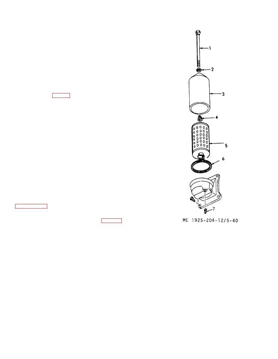
(a) Remove drain plug (7, fig. 5-40) and
drain oil from the filter.
1.
Stud
5.
Filter element
2.
Gasket
6.
Washer, nonmetallic
3.
Shell
7.
Plug, drain
4.
Spring
Figure 5-40. Lubricating oil filter .
5-48
|
||
|
||


