
| Tweet |

Custom Search
|
|

|
||
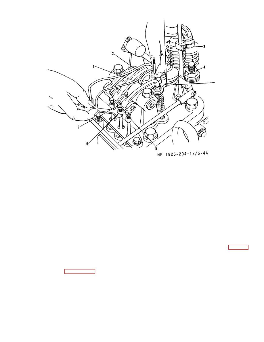 1.
Guide follower
5.
Push rod locknut
2.
Injector rocker arm
6.
Push rod, upper
3.
Timing gage
7.
Rocker arm clevis
4.
Injector body
Figure 5-44. Timing fuel injectors.
(4) Adjust the injector rocker arm (2) by means of
5-14.
Fuel Transfer Pump and Lines
the screw adjustment on the upper end of the push rod (6),
a. General. The fuel transfer pump is a positive
until the lowest surface of the timing gage head, when rotated,
displacement gear type pump, mounted on the aft lower end
Sill just pass over the top surface of the plunger follower guide
of the blower. The pump maintains a minimum fuel pressure
(1). Tighten locknut on push rod and recheck with timing
of 20 psi at the fuel inlet passage.
gage. The timing gage must be held perpendicular to top
b. Removal.
surface' of the injector body.
(1) Disconnect fuel pump inlet and outlet
connections and move fuel lines away.
CAUTION
(2) Remove the three nuts that hold the fuel pump
body to engine block and withdraw pump from engine blower.
When the above timing operation is
c. Disassembly.
carried out on an engine on which an
(1) Remove the eight capscrews (9, fig. 5-45)
injector has been installed, do not run
and lockwashers (10) securing fuel pump cover (8) to fuel
the engine until after the injector racks
pump body (4) and withdraw the cover.
have been properly positioned.
(5) Adjust the injector control racks according to
the procedures laid down in paragraph 5-16. .
5-55
|
||
|
||


