
| Tweet |

Custom Search
|
|

|
||
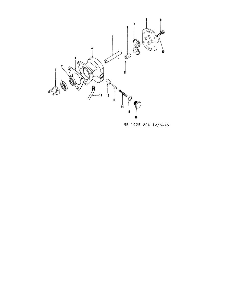 1.
Fork. fuel pump coupling
10.
Lockwasher
2.
Fuel pump seals
11.
Ball
3.
Gasket
12.
Valve
4.
Pump body
13.
Pin
5.
Drive shaft
14.
Spring, helical
6.
Driven shaft
15.
Gasket
7.
Drive gear
16.
Plug
8.
Pump cover
17.
Pump drain line
9.
Capscrew
Figure 5-45. Fuel transfer pump.
(2) Withdraw the driven shaft (6) and gear from
(4) Inspect relief valve for burrs or score marks.
pump body as an assembly. Lift drive shaft (5) and gear (7)
If defective, install new valve.
from pump body.
(5) Inspect finished surfaces of pump cover and
(3) Remove relief valve retaining plug (16), spring
body. These parts must be flat and free from burrs and score
(14), pin (located in center of spring), and valve (12).
marks.
(4) Place pump body between padded jaws of a
e. Assembly.
vise.
(1) Position inner seal (2) in seal recess of pump
(5) Remove both seals (2) by driving out with a
with sealing edge toward center of pump body.
wooden dowel.
(2) Position outer seal (2) against inner seal with
d. Cleaning, Inspection, and Repair.
sealing edge away from pump.
(1) Wash all parts in clean fuel oil and dry with
(3) Clamp pump body in soft jaws of vise with
compressed air.
relief valve opening up. Place valve in valve opening with
(2) Inspect gears for wear, score marks or nicks.
open end up. Insert spring in valve followed by the pin. Place
If gears are damaged in any way, replace.
a new gasket (15) over valve retaining plug and replace plug
(3) Inspect shafts for score marks or wear. If
in body.
defective, replace.
(4) Insert fuel pump drive shaft (5) and gear
5-56
|
||
|
||


