
| Tweet |

Custom Search
|
|

|
||
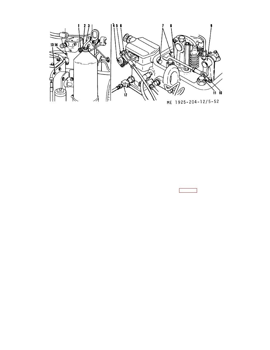 1.
Spring, governor control retracting
8.
Rod, governor subcap fuel
2.
Bolt, governor control lever
9.
Lever, injector control tube
3.
Lever, governor control
10.
Washer
4.
Shaft, governor speed adjusting
11.
Retainer spring
5.
Clevis pin
12.
Tube assembly
6.
Link, governor control shaft
13.
Bolt
7.
Bolt, subcap to cylinder head
14.
Governor base
Figure 5-52. Hydraulic governor mountings.
(2) Slip end of fuel rod off pin in injector control
NOTE
tube lever.
Handle the governor carefully; especially
(3) Disconnect, at the governor, tube assembly
avoid striking the end of the drive shaft.
(12) between cylinder block and governor base (14).
Such treatment might move the collar on
(4) Remove clevis pin (5) holding governor control
the drive shaft and result in excessive
lever (3) to throttle control link (6). Separate link from lever.
end play of the ball head and shaft.
Do not detach lever from governor speed adjusting shaft (4).
(5) Remove the three screws and lockwashers
(1) Place a new gasket over studs on governor
holding governor cover and subcap to governor case. (Some
drive housing flange. Set governor assembly on drive flange
models have two Allen setscrews in the subcap holding
with opening for oil line into governor pointing in same
subcap in position during adjustment).
direction as drive shaft of drive housing.
(6) Remove two bolts (7) and lockwashers
(2) Secure governor assembly to drive housing
holding governor subcap to cylinder head.
using a lockwasher and nut on each of the four studs. Draw
(7) Lift up on subcap assembly until a definite
nuts down uniformly and after tightening, revolve the drive
snap indicates that fuel rod has been released from terminal
shaft of the governor drive to check for binding. Parts must
lever within the governor base. Remove subcap assembly,
move freely without bind.
pulling fuel rod (8) out of hole in cylinder head. Remove
(3) If governor cover and subcap are installed
gasket between subcap and governor case.
remove from governor case.
(8) Remove four stud nuts holding governor
(4) Place gasket on top flange of governor case.
assembly to governor drive assembly and lift governor off
(5) Pick up subcap and insert long projecting end
studs and away from engine. Remove gasket between
of fuel rod through hole in cylinder head and position subcap
governor and governor drive.
over governor case. (Secure subcap to case on models
having provisions for same).
5-65
|
||
|
||


