
| Tweet |

Custom Search
|
|

|
||
 (8) Remove all capscrews securing the heat
KEY to fig. 5-55:
15.
Capscrew
exchanger to the engine, then lift heat exchanger to a suitable
1. Gasket
16.
Hose
work area.
2. Core
17.
Hose clamp
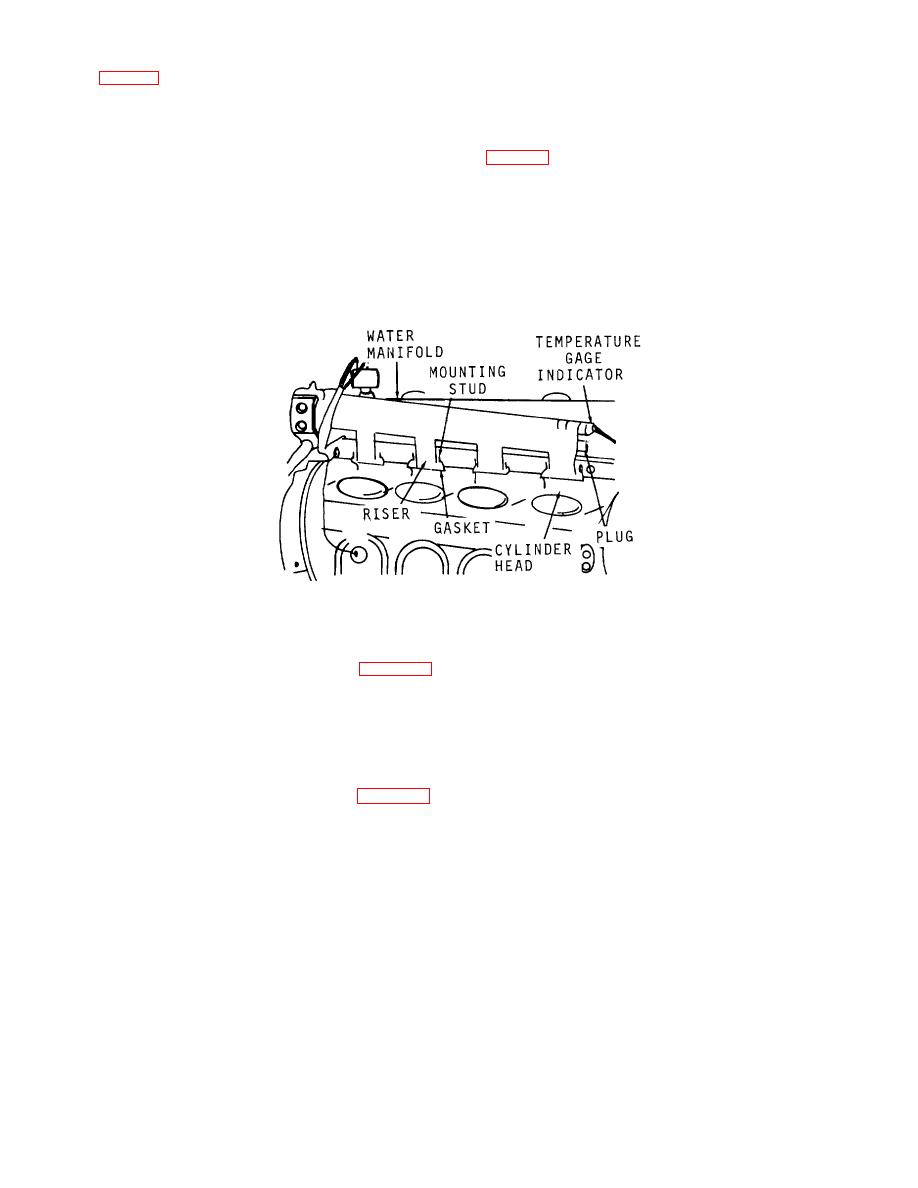
(9) Remove the water manifold as follows:
3. Gasket
18.
Elbow
(a) Disconnect temperature gage indicator
4. Cover
19.
Flange
5. Lockwasher
20.
Gasket
(b) Remove two nuts from studs at the four
6. Capscrews
21.
Housing
risers, then lift water manifold from the cylinder head.
7. Capscrews
22.
Gasket
Remove the four gaskets.
8. Plug
23.
Lockwasher
9. Gasket
24.
Gasket
10. Spring
25.
Lockwasher
11. Valve
26.
Bolt
12. Tube assembly
27.
Capscrew
13. Gasket
28.
Lockwasher
14. Lockwasher
Figure 5-56. Typical water manifold mounting.
c. Disassembly.
d. Cleaning, Inspection, and Repair.
(1) Remove raw water components as follows:
(1) Wash all hardware in clean fuel oil and blow
(a) Remove capscrews (20, fig. 5-54),
dry with compressed air.
cover (15), and gasket (14).
(2) Clean oil cooler core by directing a jet of
(b) Remove retainer (6), gasket (10), and
steam into the inlet side. Wash the interior with water after
rings (11), then pry on flange of core (13) and remove it from
steaming, warm the unit to remove all traces of water.
the heat exchanger. Remove the electrode assemblies (1)
(3) If the raw water core, or the water manifold
from covers (15 and 7).
are scaled, clean by soaking in a solvent (FED SPEC P-D-
(2) Remove oil cooler and fresh water
680), then blow dry with compressed air. If some scale is still
components as follows:
there, use a wire brush and remove all traces. Clean all
(a) Remove capscrews (27, fig. 5-55),
gasketing surfaces thoroughly.
lockwashers (28), then remove fresh water suction line flange
(19) and gasket (20).
NOTE
(b) Remove
two
capscrews
(7),
The manufacturer recommends an
lockwashers (23) and bypass valve housing (21). Then
alternate procedure, with a mixed scale
remove gasket (22) from housing.
solvent consisting of (1/3) muriatic acid
(c) Remove capscrews (6), lockwashers
and (2/3) water to which one-half (1/2)
(5), cover (4), and gasket (3).
pound of oxalic acid has been added for
(d) Pull core (2) from the heat exchanger
each 2 1/2 gallons of the solution.
housing, then remove gasket (13).
Remove the core or manifold when the
(e) Remove plug (8), gasket (9), spring
bubbling and foaming stops.
This
(10), and valve (11) from oil bypass valve housing (21).
usually takes from 30 to 60 seconds,
then flush thoroughly with clean hot
water under pressure.
5-71
|
||
|
||


