
| Tweet |

Custom Search
|
|

|
||
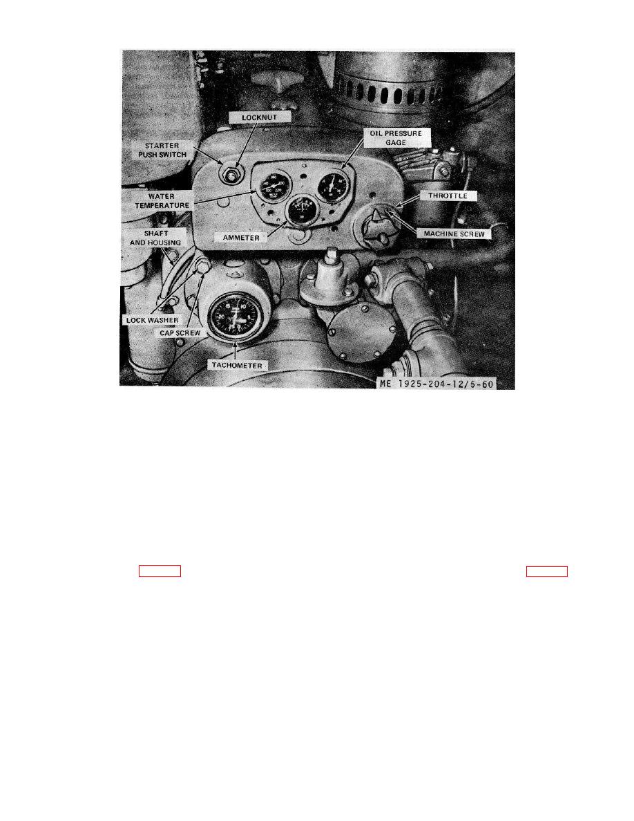 Figure 5-60. Engine instrument panel.
(b) Remove locknut nameplate, lockwasher and plain
(2) Inspection.
nut, then remove switch from rear panel.
(a) Inspect glass for crack, and dial for clarity in
(2) Inspection.
reading. Replace a gage with broken glass or unreadable
(a) Inspect the switch terminals for corrosion or
dial.
broken mount. Replace a defective push switch.
(b) Install the gage in place on opposite engine and
(b) Check for continuity across terminals while the
compare reading. Replace a gage with an inaccurate reading.
button is pushed in. If no circuit is indicated, replace the
(3) Installation. Install by reversing the procedure in
switch.
step (1) above.
(3) Installation.
Install the starter push switch by
d. Water Temperature Gage.
reversing the procedure in step (1) above.
(1) Removal.
c. Oil Pressure Gage.
(a) Disconnect the capillary tube and holding clips
from the cylinder head.
(1) Removal.
(b) Remove attaching hardware, then remove gage
(a) Disconnect, or remove the flexible tube from rear
and capillary tube through the panel opening (fig. 5-60).
of the oil pressure gage (fig. 5-60).
(b) Remove clamp securing the oil pressure gage to
rear of the instrument panel, then withdraw the oil pressure
gage from front of the panel
5-80
|
||
|
||


