
| Tweet |

Custom Search
|
|

|
||
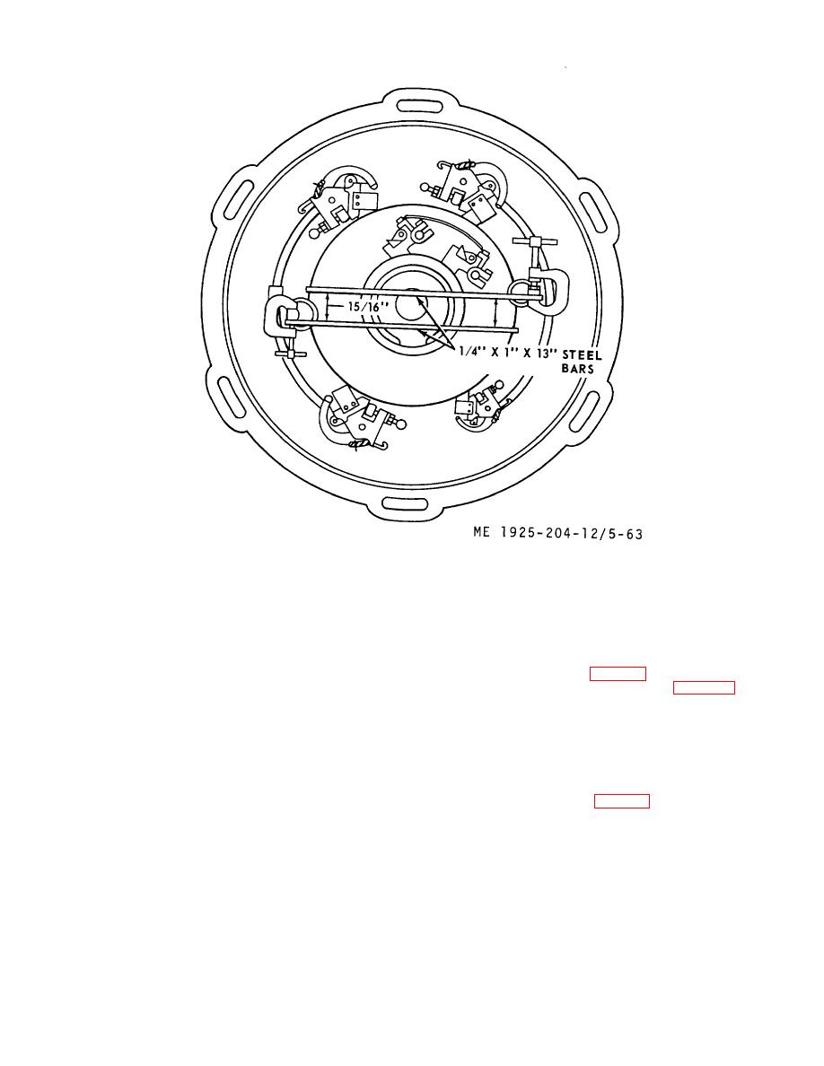 Figure 5-63. Stud alignment.
f. Assembly.
CAUTION
(1) Slip bearing cap (25) on commutator end of armature
Do not saturate windings with solvent.
shaft.
(2) Install bearing collar (24) on armature shaft.
(2) Check brush tension springs; replace springs that
(3) Press bearing (22) on armature shaft.
cannot be adjusted to proper tension.
(4) If brush holder studs were removed, install brush
(3) Inspect brush holder mounting studs, check
holder assembly and adjust (fig. 5-63).
insulation resistance from stud to frame; replace defective
(5) Install commutator endbell (26, fig. 5-62); align
insulating sleeves. When installing new sleeves or studs,
marking on endbell with marks on field frame and fasten
avoid cracking sleeves.
endbell with bolts (27).
(4) Check ball bearings by holding inner race and turning
(6) Position bearing cap (25) so that holes in bearing
outer race with fingers. Replace bearing if it binds or sticks.
cap are over holes in commutator endbell. Insert bolts (23)
(5) Inspect field and armature windings for damaged
and tighten.
insulation. Report damage to higher maintenance level or
(7) Install fan and drive disc assembly (12) and fasten
replace generator assembly.
with mounting bolts (14).
(6) Inspect commutator for pitting or grooving.
If
(8) Align brush holders (fig. 5-64).
commutator is badly grooved, armature must be chucked in a
lathe and commutator turned down. After turning, undercut
mica to a depth of 1/32 to 3/64 inch.
5-84
|
||
|
||


